Section 1. General Information
page 1-2
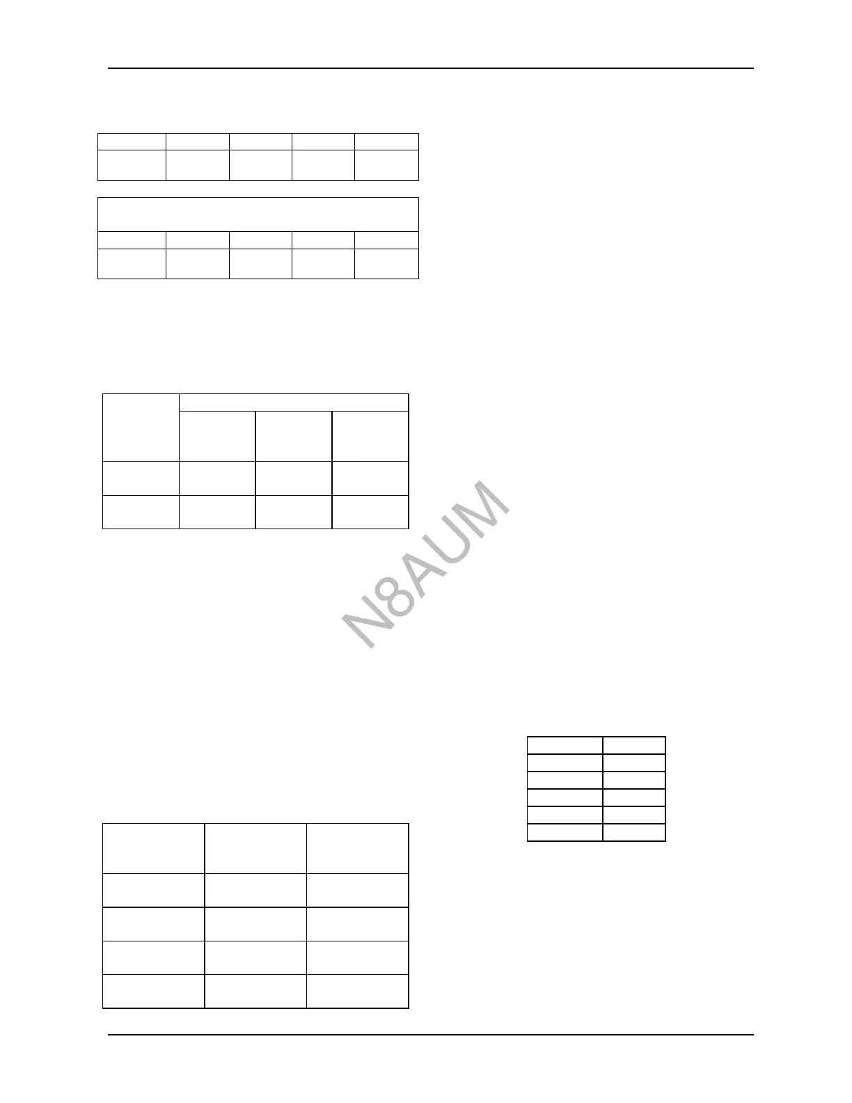
1-2.4 Crest Factor:
Range 1mV 3mV 10mV 30mV
Crest
Factor*
420 to 42 42 to 14 14 to 4.2 4.2 to 1.4
With 100:1 Divider
Range
0.1 V 0.3 V 1 V 3 V
Crest
Factor*
420 to 42 42 to 14 14 to 4.2 4.2 to 1.4
*Maximum permissible ratio of peak to rms value of
voltage
1-2.5 Accuracy (Frequency Effects):
The maximum uncertainty is the sum of frequency
effects and temperature effects.
Range Frequency
(FS) 10 kHz to
150 MHz
150 MHz
to 700
MHz
700 MHz
to 1.2
GHz
100 mV to
300 mV
±(1% FS +
1% Ind)
±(1% FS +
5% Ind)
±(1% FS +
12% Ind)
1 V to 3 V ±(1% FS +
1% Ind)
±(1% FS +
5% Ind)
±(1% FS +
12% Ind)
Note: FS = full scale; Ind= indication
*At 1 mV and below add ±1% FS
Ref. conditions: 20 to 25°C, 10 min warm-up
Measurements are referenced in 50 ohm systems using
the Ballantine 34402A probe with Model 5340A Tee
adapter and Ballantine 31-10189-1 precision 50 ohm
termination. Voltage is measured at the input
connector of the tee.
VSWR: 1.1 to 300 MHz, 1.2 to 1 GHz, and 1.3 to 1.2
GHz.
1-2.6 Temperature Effects (at 1 MHz):
A heater system in the detector probe maintains
detector temperature in the range of 23° to 28°C at all
ambient temperatures to 0°C.
Ambient With Probe
Heater Set To
25°C
With probe
heater set to
35°C
30°C to 40°C Add ±4% of
indication
Add ±3% of
indication
25°C to 30°C Add ±1% of
indication
Add +0.5% of
indication
10°C to 15°C Add ±1% of
indication
Add ±1% of
indication
0°C to 10°C Add ±4% of
indication
Add ±4% of
indication
1-2.7 Meter:
The instrument incorporates an analog meter for
readout. Three scales and antiparallax mirror are
provided. The 0 to 10 scale is uppermost and is 4.4
inches long. The 0 to 3 scale is below, followed by a -
10 to +3 dBm scale. dBm reference is .221 V equals 0
dBm (0 dBm = 1 mW into 50 ohms).
1-2.8 Indicator unrest: (1 mV FS range only)
Unrest of the meter pointer will be < ±1% FS above
uV indication, <±2% FS between 300 and 600 uV and
< ±5% FS from 100 µV to 300 µV.
1-2.9 Response Time and Overload Recovery:
Less than 1 second meter response on 3 mV to 3 V
ranges, increasing to 3 seconds rise time on 1 mV
range. The instrument recovers within 10% of final
indication within one minute after removing 3 V (rms)
overload on 1 mV range. A response switch permits
selection of slow or normal response times when
measuring input signals having time varying amplitude
components.
1-2.10 Detector Probe:
A detachable probe containing the RF detector is
provided. The shielded probe’s cable is 4 feet (1.2
meters) long and terminated in a quick disconnect
locking connector at the front panel. A Ground Clip
Lead is provided with the probe.
1-2.11 Probe Input Impedance:
Typical values measured at 21° to 25°C with probe
heater set to 25°C. Option 40 provides probe
(34403A) using diodes with equal capacitance and
higher input resistance limits.
1-2.12 Probe Input Shunt Capacitance at 100 kHz:
0 mV 2.8 pF
30 mV 2.7 pF
100 mV 2.5 pF
300 mV 2.3 pF
1 V 2.0 pF
3 V 1.8 pF
1-2.13 VSWR:
VSWR using probe with non-loading "T" connector in
a 50 ohm system is no greater than 1.3 from 10 kHz to
1.2 GHz.
1-2.14 Power Sensitivity:
Probe shall not require more than 1.8 nW of input
power at 300 µV input voltage when used with a non-
loading "T" connector in a 50 ohm system.
N8AUM
 Loading...