Do you have a question about the B&B ARMR 773 Series and is the answer not in the manual?
Welcome message and introduction to B&B ARMR's security solutions and services.
Essential safety precautions and compliance with OSHA, local, and international standards.
Explanation of hazard symbols (DANGER, WARNING, CAUTION, NOTE, TIP) used in the manual.
Glossary of common industry acronyms and their meanings used in the manual.
B&B ARMR contact details for technical support and general inquiries.
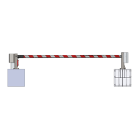
Introduction to the Model 773 barrier, its purpose, and key components.
Details on the aluminum arm, its construction, safety tape, and energy absorption.
Description of drive and receiver stanchions, including hinge and latching mechanisms.
Information on the 773ED/ER electric drive, actuator, and control components.
Details on the 773HD/HR hydraulic drive, HPU unit, and control components.
Information on the 773MD manual operation and potential optional electrical components.
List of available options and additional safety devices for the Model 773 barrier.
Describes the procedure to set up and configure the Model 773 barrier for first-time operation.
Important considerations before site excavation and barrier installation, including site inspection and soil requirements.
Overview of the eight-step installation process for Model 773 barriers.
Details excavation dimensions, pad positioning, soil compaction, and concrete requirements.
Instructions for installing conduit for power/control circuits and constructing rebar cages.
Details on placing retention plates and anchor bolts into the rebar cage.
Instructions for placing the rebar cage with anchor bolts and retention plates into the excavation.
Using retention plates as templates to secure anchor bolts for the concrete pour.
Instructions for filling excavations with concrete, finishing, and allowing it to cure.
Procedure for lifting and securing drive and receiver stanchions onto anchor bolts.
Refer to HPU Installation manual for hydraulic unit installation procedures.
Refer to Electric/Hydraulic Drive Installation and O&M manual for control system details.
Instructions for lifting, aligning, and inserting the hinge pin for the barrier arm.
Verifying arm alignment with the receiver stanchion and adjusting bearings if binding occurs.
Detailed steps for loosening bearing bolts and using adjustment screws to correct arm binding.
Ensuring hinge pin is flush and tightening bearing set screws.
Centering the arm on the hinge pin and tightening arm cradle set screws.
Connecting the hydraulic cylinder or electric actuator to the drive stanchion and arm.
Installing and aligning the limit switch within the drive stanchion.
Description of the four sensors (Up Slowdown, Up Stop, Down Stop, Down Slowdown) and flags.
Explains how the sensor bracket locks sensors and the flag collar secures to the hinge pin.
Adjusting the flag collar to match the 'FULL DOWN' position as illustrated.
Manually moving the arm to the full upright position and adjusting the flag collar for the 'FULL UP' position.
Installing sheetmetal covers, ensuring they do not interfere with arm operation or pinch wires.
Connecting hydraulic lines to the cylinder and control enclosure, referencing HPU manual.
Locking the barrier arm to the receiver stanchion using the supplied security pin.
Follow specific instructions for installing options mentioned in Section 2.
Step-by-step guide for installing traffic lights onto the stanchion.
Connecting traffic light wires to the EPU/HPU PLC controller output module.
Checklist to verify all installation steps are completed before operating the barrier.
Detailed sequence for starting up the barrier, including disabling safety devices and cycling the unit.
Tables providing guidance for identifying and correcting common problems with the Model 773 Series.
Listing of various technical drawings related to the Model 773 barrier installation.
Diagram showing the general layout of the 773E/H Series Crash Barrier components.
Detailed drawing of foundation dimensions and clear opening specifications for 773E/H Series.
Diagram illustrating the general layout of the 773M Series Crash Barrier components.
Detailed drawing of foundation dimensions and clear opening specifications for 773M Series.
Detailed specifications for constructing rebar cages for the barrier foundations.
Summary of general, installation, design, and electrical specifications for Model 773.
| Brand | B&B ARMR |
|---|---|
| Model | 773 Series |
| Category | Control Systems |
| Language | English |