EasyManua.ls Logo

B&K 281 - Operating the Digital Multimeter; Interpreting Digital Displays; Instrument Power-On Procedure; Measuring DC Voltages

Default Icon
23 pages
Print Icon
To Next Page IconTo Next Page
To Previous Page IconTo Previous Page
Loading...
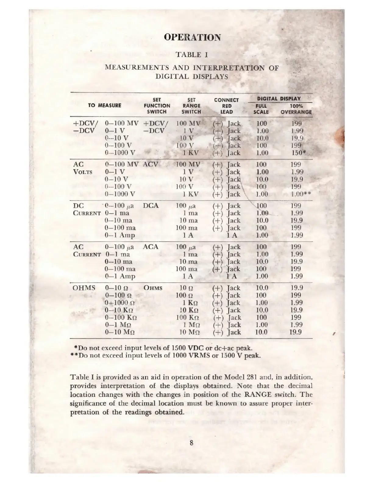
OPERATION
S
EFL
t
TABLE
I
j
е
MEASUREMENTS
AND
INTERPRETATION
OF
=
DIGITAL
DISPLAYS
ae
<
TEE
T
SE
SET
CONNECT
DIGITAL
DISPLAY
|
À
TO
MEASURE
FUNCTION
RANGE
RED
.
FULL
100%
A
SWITCH
SWITCH
»
LEAD
-.
SCALE
OVERRANGE
.
+DCV/
0-100MV
+DCV/
100MW
(4)
Jack
100
199
—
-DCV
0-1V
—DCV
ІМ
e
(F)
Jack
1.00
1:99
0-10
V
10V
(+)
Jack
10:0
19.9
|
0—100
V
100
У.
-(-)
Jack
-
100
19%
|
А.
0—1000
У.
=
IKV
(+)
Jack
1.00
150%.
AC
0—100
MV
ACV
100
MV
(+)
Jack
100
199
Vorrs
0-1У
1V
(+)
Jac
1.00
1.99
0—10
V
10
V
(+)
Jac
10.0
199
-
0—100
V
100
V
(+)
E
100
199
0—1000
V
1KV
(+)
Jack
\
1.00
1.00**
DC
“0-100
na
РСА
100
na
(+)
Jack
7100
199
CURRENT
0—1
ma
1
ma
(+)
Jack
1.00—
1.99
0—10
ma
10
ma
(+)
Jack
10.0
19.9
0—100
ma
100
ma
(+)
Jack
100
199
0—1
Amp
1A
1A
1.00
1.99
AC
0-100
ya
АСА
100
ua
(+)
Jack
100
199
CURRENT
0—1
ma
]
ma
(+)
Jack
1.00 1.99
0—10
ma
10ma
(+)
Jack
10.0 19.9
0—100
ma
100
ma
(+)
Jack
100
199
0—1
Amp
1A
1A
1.00
1.99
OHMS
0-109
Onms
100
(+)
Jack
10.0
19.9
0—100
о
1000
(+)
Jack
100
199
0--1000
о
1Ко
(+)
Jack
1.00
1.99
0—10
Ko
10KQ
(+)
Jack
10.0
19.9
0—100
Ka
100KQ
(+)
Jack
100
199
0—1
Mo
1Mo
(+)
Jack
1.00
1.99
0—10
Mo
10Mo
(+)
Jack
10.0
19.9
Р
*Do
not
exceed
input
levels
of
1500
VDC
or
dc+ac
peak.
**Do
not
exceed
input
levels
of
1000
VRMS
or
1500
V
peak.
|
Table
I
is
provided
as
an
aid
in
operation
of
the
Model
281
and,
in
addition,
1
provides
interpretation
of
the
displays
obtained.
Note
that
the
decimal
location
changes
with
the
changes
in
position
of
the
RANGE
switch.
The
significance
of
the
decimal
location
must
be
known
to
assure
proper
inter-
pretation
of
the
readings
obtained.
Аааа
_

Related product manuals