EasyManua.ls Logo

B&K 281 - ADC Process Explained; Digital Counter Role; Display Indicator Function; Voltage Attenuator Circuit

Default Icon
23 pages
Print Icon
To Next Page IconTo Next Page
To Previous Page IconTo Previous Page
Loading...
oe
*
voltage
in
millivolts;
i.e.
OmV
=
Ises,
1OmV
=
10
pulses,
100mV
=
100
pulses,
etc.
;
N
om
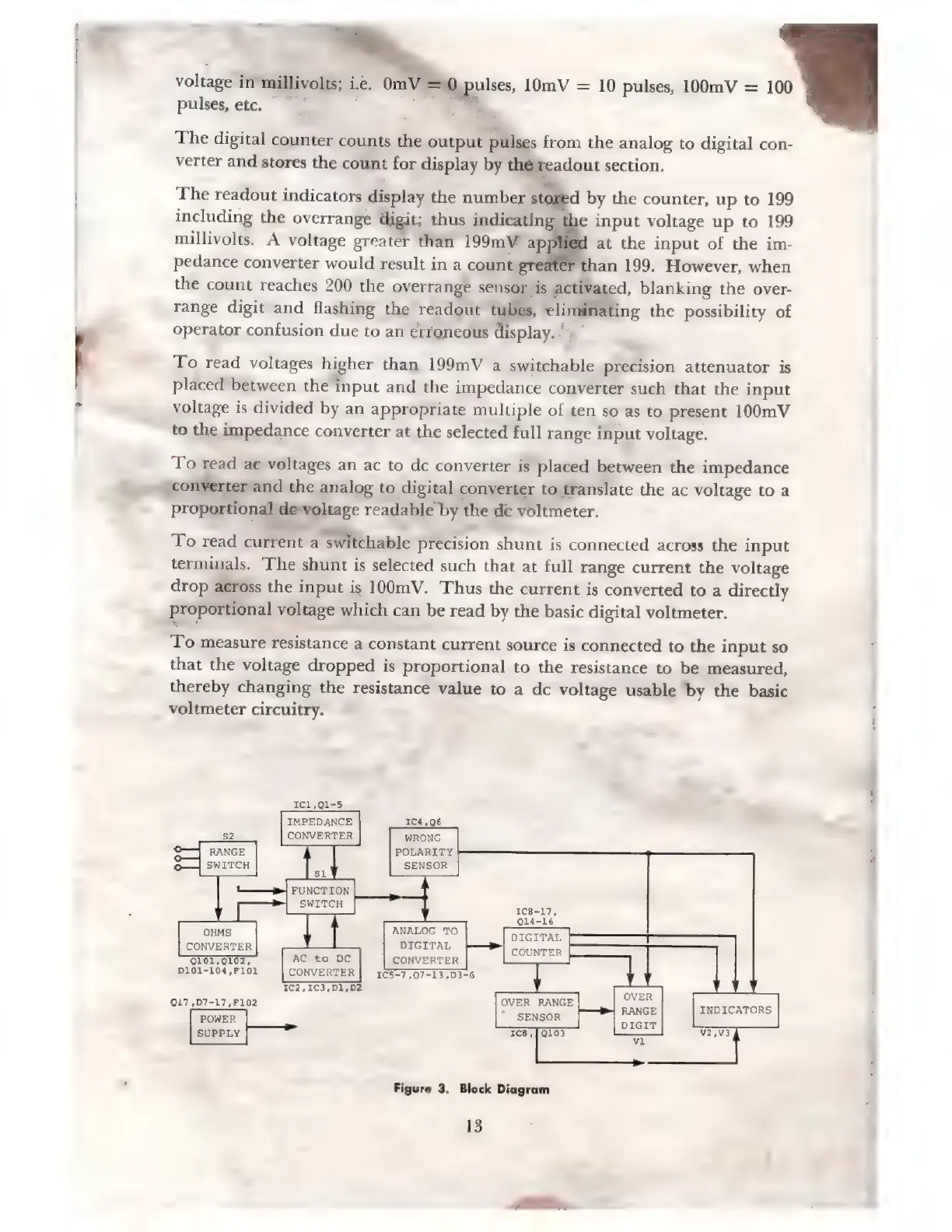
The
digital
counter
counts
the
output
pulses
from
the
analog
to
digital
con-
verter
and
stores
the
count
for
display
by
théfreadout
section.
The
readout
indicators
display
the
number
stor
including
the
overrange
digit;
thus
indicating
millivolts.
A
voltage
greater
than
199mV'
ар
at
the
input
of
the
im-
pedance
converter
would
result
in
a
count
greater
than
199.
However,
when
the
count
reaches
200
the
overrange
sensor
is
activa
ed,
blanking
the
over-
range
digit
and
flashing
the
readout
tubes,
uc
M
the
possibility
of
operator
confusion
due
to
an
erroneous
display.
=`
d
by
the
counter,
up
to
199
e
input
voltage
up
to
199
To
read
voltages
higher
than
199mV
a
switchable
precision
attenuator
is
placed
between
the
input
and
the
impedance
converter
such
that
the
input
voltage
is
divided
by
an
appropriate
multiple
of
ten
so
as
to
present
100mV
to
the
impedance
converter
at
the
selected
full
range
input
voltage.
To
read
ac
voltages
an
ac
to
dc
converter
is
placed
between
the
impedance
-—conyerter
and
the
analog
to
digital
converter
to
translate
the
ac
voltage
to
a
proportional
devoltage
readable
by
the
dc
voltmeter.
To
read
current
a
switchable
precision
shunt
is
connected
across
the
input
terminals.
The
shunt
is
selected
such
that
at
full
range
current
the
voltage
drop
across
the
input
is
100mV.
Thus
the
current
is
converted
to
a
directly
proportional
voltage
which
can
be
read
by
the
basic
digital
voltmeter.
eke
To
measure
resistance
a
constant
current
source
is
connected
to
the
input
so
that
the
voltage
dropped
is
proportional
to
the
resistance
to
be
measured,
thereby
changing
the
resistance
value
to
a
dc
voltage
usable
by
the
basic
voltmeter
circuitry.
ІСІ,01-5
IMPEDANCE
CONVERTER
#
FUNCTION
SWITCH
WRONG
POLARITY
SENSOR
IC8-17,
014-16
OHMS
BNALOG
TO
DIGITAL
CONVERTER
DAD
COUNTER
ЭТӘ,
АС
to
DC
CONVERTER
D101-104,F101
CONVERTER
1C5-7,07-13,D3-6
E
OVER
RANGE
SVER
017
,D7-17,F102
RANGE
INDICATORS
“
SENSOR
Q103
DIGIT
POWER
SUPPLY
Figure
3.
Block
Diagram
13

Related product manuals