DA
DB
DG
SLD
+24V
24G
FG
DA ④
DB ②
DG ③
SLD①
+24V①
24G③
FG
④ DA
② DB
③ DG
①SLD
①+24V
③24G
FG
DA
DB
DG
SLD
FG
Terminators Terminators
Master unitRCD22ERCD22TRemote unit
External
device
Blue
White
Yellow
SLD
Brown
Blue
FG
Blue
White
Yellow
SLD
Brown
Blue
FG
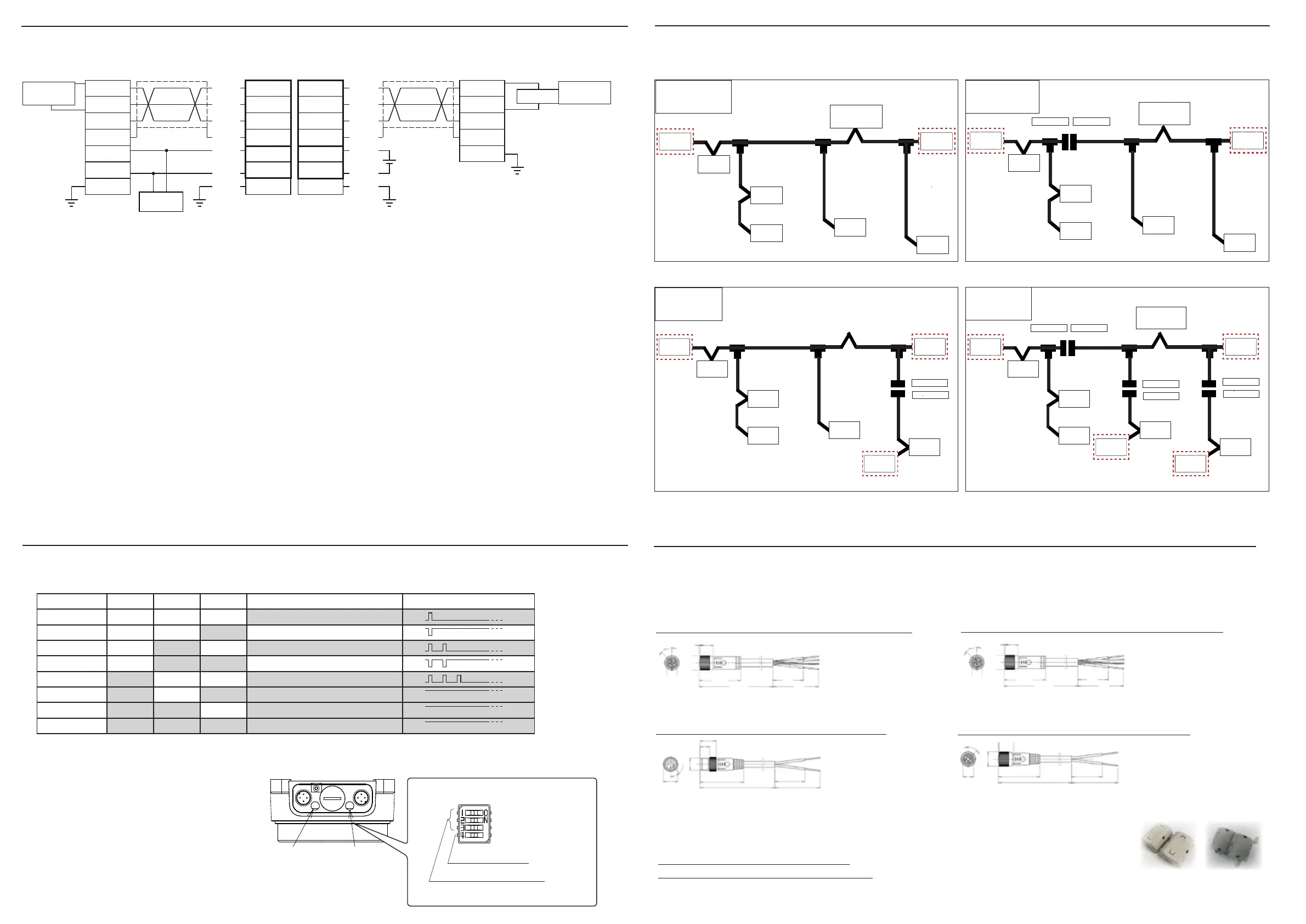
Please read the CC-Link Installation Manual carefully when wiring.
The following is a wiring example of a T-branch without repeater function.
- The cable color in this wiring diagram shows the cable color when using the recommended connector cable. When
wiring, check the instruction manual of the cable you actually use before wiring.
- Connect "Terminators" between DA-DB of the last unit on the CC-Link network.
- When this unit mounted on the both end of CC-Link network, please set the Dip switch SW4 to ON.(Refer to the
followiing Setting for Switch and Status LED indication (Remote part/Base part part)
・When installing with T-branch wiring, set the communication speed to 625 kbps or less.
- For wiring of external power unit 24V DC to FG, please return to wiring.
Connect "+" of power unit +24V DC to a terminal indicated [+24V] , "-" to [24G].
- Always use a constant voltage power supply such as a switching power supply.
(Use of a power supply with a ripple greater than the rated value, such as a full-wave rectier power supply, may cause
malfunction.)
- Please set the cable length to consider the total length of the entire network according to CC-Link manual.
- When the Remote part and the Base part are not facing each other, no signal is sent from the Remote part, but there is
no problem in communication on the Base part.
Wiring sample
Wiring diagram between master unit and slave
Setting for Switch and Status LED indication (Remote part/Base part part)
Communitation speed is set with S W1~3, when SW4 is turned on, Terminator(110Ω)can be used.
ON
OFF
SW4:終端抵抗(110Ω)ON/OFF
SW3~1:ボーレート設定
*Always make changes to the DIP switches
with the power turned off.
If changed while energized, communication
is disabled and the status LED blinks at 0.5
second intervals.
*If the dip switch lid is opened, close it tightly
to prevent water from entering.
Initial value
(default)
SW 1:OFF
SW 2:OFF
SW 3:ON
SW 4:ON
Status LED(Green/Yellow)
SW1 ~ 3:commnunication spped set up
SW4:Terminator(110 Ω )ON/OFF
ONOFF
Pwer LED(Green)
No. = Pin assignment (refer to the dimensional outline drawing)
通常
master
station
Terminator
Terminator
slave
station
slave
station
slave
station
slave
station
slave
station
master
station
支線分断
Terminator
Terminator
SW4 → OFF
SW4 → ON
Terminator
slave
station
slave
station
slave
station
slave
station
slave
station
幹線分断
Terminator
Terminator
SW4 → ON
SW4 → ON
master
station
slave
station
slave
station
slave
station
slave
station
slave
station
複数設置
Terminator
Terminator
Terminator
SW4 → ON
SW4 → ON
SW4 → OFF
SW4 → ON
SW4 → OFF
SW4 → ON
Terminator
master
station
slave
station
slave
station
slave
station
slave
station
slave
station
Remote part
Base part
Terminator
(110 Ω)
Terminator
(110 Ω)
■ for RCD22T(Remote part)
bending radius = 24mm
bending radius = 46mm
bending radius = 24mm
White Gray
bending radius = 46mm
■ for RCD22E(Base part part)
Communication cable VA-4DSX5CCG4 (M12/4 pin female,5m)
Power cable :TM-4DBX5HG2-1/3 (M12/4 pin male,5m)
Power cable:TM-4DSX5HG2-1/3 (M12/4 pin male, 5m)
Ferrite clamp(White):DK-Z/RFC-H13
45°
M12 × 1.0
φ 14.5
1
13
41.7
(5m)
30
45
45°
φ 14.5
M12 × 1.0
9
15.5
42
(5m)
30
45
45°
M12 × 1.0
φ 14.5
1
15.5
40
(5m)
30
45
1----------------------SLD
2---------------------- White
3----------------------Yellow
4---------------------- Blue
1----------------------Brown
2---------------------- ×
3----------------------Blue
4---------------------- ×
1----------------------Brown
2---------------------- ×
3----------------------Blue
4---------------------- ×
Ferrite clamp(Gray):DK-Z/E04SR401938
Communication cable VA-4DSX5CCG4 (M12/4 pin female、5m)
45°
M12 × 1.0
φ 14.5
1
13
41.7
(5m)
30
45
1----------------------SLD
2---------------------- White
3----------------------Yellow
4---------------------- Blue
Communication speed
SW3 SW2 SW1 LED status Interval when LED blinks
156kbps OFF OFF OFF
Lighting once every 2 seconds.
625kbps OFF OFF ON
Turning o once every 2 seconds.
2.5Mbps OFF ON OFF
Lighting twice every 2 seconds.
5Mbps OFF ON ON
Turning o twice every 2 seconds.
10Mbps ON OFF OFF
Lighting 3 times every 2 seconds.
--- ON OFF ON LED keeps on when set error
--- ON ON OFF LED keeps on when set error
--- ON ON ON LED keeps on when set error
■
Setting for Switch
ON
OFF
ON
OFF
ON
OFF
ON
OFF
ON
OFF
ON
OFF
ON
OFF
ON
OFF
devide
the drop line
multiple
installations
Normal
wiring
devide the
trunk line
Optional parts
【communication cable / power cable】
Recommended connector cable is available as an option. Please use in combination with the remote coupler system.
[Ferrite clamp]
The included Ferrite clamp is available as an option in case it is damaged or lost.
 Loading...