Do you have a question about the B&R X90 and is the answer not in the manual?
Crucial safety precautions, intended use, handling, and disposal instructions.
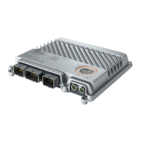
Introduces the X90 mobile product line concept and its suitability for harsh environments.
Details on processor options, general information, order data, and technical specifications.
Discusses decentralization benefits and wiring solutions for mobile automation.
Covers error detection methods using LEDs and software for quick troubleshooting.
Explains how I/O mapping and module configuration provide adaptable solutions.
Provides detailed physical dimensions of the mobile system for installation planning.
Essential guidance on proper mounting, clearances, and connector handling for optimal performance.
Details on necessary overcurrent protection for various pins and fuses for safe operation.
Describes the modular design, robust housing, and key features for flexibility and durability.
Step-by-step instructions for mounting, dismounting, and connecting accessories.
Provides an alphabetical and grouped listing of available modules with their short descriptions.
Details on X90 mobile CPUs, general information, order data, and technical specifications.
Information on analog output modules including general data, order data, and technical specifications.
Covers the X90CM480 module for vibration analysis and condition monitoring of machinery.
Technical data and configuration details for the 10-channel digital input option board.
Information on the X90PO210.08-00 PWM option board, including technical data and configuration.
Details on the X90AT910.0x-00 option board for resistance, voltage, temperature, digital input, and PWM measurements.
Lists B&R and Molex accessories, including bus controllers, installation tools, and cables.
Specifications for X67 POWERLINK/Ethernet cables with RJ45 to M12 and M12 to M12 connectors.
Details on the X90TB100.03-00 connector set for CMC connectors, including technical data.
Lists UN/ECE and CE markings, indicating compliance with relevant standards.
Details various EMC, electrical, mechanical, climatic tests, and degree of protection standards.
Specifies requirements for immunity to disturbances, including ESD and electromagnetic fields.
Outlines industry requirements for immunity to disturbances and emissions.
Provides access to module-specific information like firmware version, hardware variant, and serial number.
| Series | X90 |
|---|---|
| Power Supply | 24 VDC |
| Processor | Intel Atom |
| Display | Optional TFT display |
| Resolution | Varies by model |
| Touchscreen | Optional |
| USB Ports | USB 2.0 and/or USB 3.0 |
| Serial Ports | RS232, RS485 |
| Communication Protocols | CAN |
| Dimensions | Varies by model |
| Weight | Varies by model |
| Certifications | CE, UL |