Do you have a question about the Bang & Olufsen BeoSound 9000 MKIII and is the answer not in the manual?
| Type | CD Player |
|---|---|
| Model | BeoSound 9000 MKIII |
| Disc sizes | 12 cm, 8 cm |
| Number of Discs | 6 |
| Frequency range | 20 Hz - 20 kHz |
| Signal-to-noise ratio | > 100 dB |
| Harmonic distortion | < 0.01% |
| Power Consumption | 30 W |
| Remote Control | Yes |
| Playback Formats | CD, CD-R |
| Outputs | Analog, Digital |
| Power Supply | 220-240 V, 50/60 Hz |
| Features | Random play, Repeat |
Provides diagram references for FM/AM module.
References the diagram for the main microcomputer.
References the diagram for the mains filter.
References the diagram for the mains relay.
References the diagram for the display.
References the diagram for sledge position.
References the diagram for the right main keyboard.
References the diagram for the left main keyboard.
References the diagram for the secondary keyboard.
References the diagram for the IR receiver.
References the diagram for the ML interface.
References the diagram for the headphone.
References the diagram for the clamper position.
References the diagram for left light indication.
References the diagram for right light indication.
References the diagram for the end stop detector.
References the diagram for safety TX.
References the diagram for safety RX.
References the diagram for the lamp.
References the diagram for IR transmitter and tacho clamper.
References the diagram for IR receiver and tacho clamper.
References the diagram for input/output select and sound adjustment.
References the diagram for the power supply.
References the diagram for motor control.
References the diagram for the lid motor.
References the diagram for the CD VAM 1250 mechanism.
References the diagram for turn table motor control.
References the diagram for the CD mechanism.
Details the BeoSound 9000 MKIII operation methods.
Describes mechanical functions like CD change time and position.
Provides technical specifications for the FM tuner section.
Provides technical specifications for the AM tuner section.
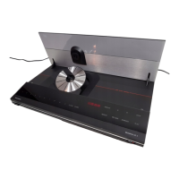
Lists technical specifications for the CD player.
Details technical specifications for the preamplifier section.
Details pin assignments and voltage levels for Master Link.
Details pin assignments and voltage levels for Power Link.
Details pin assignments and voltage levels for Audio Aux Link.
Specifies headphone connector type and power.
Details specifications for digital audio output.
Provides mains voltage and cable information.
Specifies power frequency and consumption details.
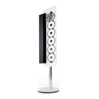
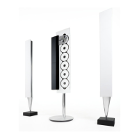
Provides physical dimensions and finish details of the product.
Lists available optional accessories for the BeoSound 9000.
Table mapping product types to transformer and PCB part numbers.
Instructions for loading CDs and basic playback controls.
Details on playing tracks, next/previous track, and pausing.
How to activate and deactivate random play mode.
Instructions for selecting multiple CDs for playback.
Manual adjustment for CD positioning.
Steps for programming a series of tracks on a CD.
How to play CDs with programmed track sequences.
Procedure for naming CDs and tracks.
How to view the list of named CDs.
Instructions for tuning and selecting radio stations.
How to select between mono and stereo reception.
How to select and play external audio sources.
Controls for volume, treble, bass, and balance.
Steps for storing and recalling preset radio stations.
Procedure for naming preset radio stations.
How to clear stored radio presets.
Method for fine-tuning radio station frequency.
How to change the radio display indication.
Instructions for setting up playback timers.
Enabling and controlling the automatic demonstration playback.
Procedure to lock or unlock the glass lid using remote control.
Instructions for setting and managing the product's clock.
Guides for centering the CD drive mechanism for different positions.
Steps to activate the product's PIN code security system.
Instructions for modifying or disabling the PIN code.
Procedure for entering PIN code after disconnection.
Guidance on what to do if the PIN code is forgotten.
Explains the coordinate system used on PCBs for component placement.
Describes how active modes are indicated in control circuits.
Explains codes used for internal and external wiring connections.
Defines the different ground symbols used in schematics.
Explains the meaning and handling of safety component symbols.
Specifies conditions and tools for measuring voltages and signals.
Highlights safety precautions for laser diodes and lithium batteries.
Explains symbols and types for fuses used in the device.
Schematic overview of the AM signal path.
Schematic overview of the FM/AM tuner signal path.
Schematic overview of the CD mechanism and control signals.
Schematic overview of signal routing for inputs and outputs.
Schematic overview of data flow and processor communication.
Schematic overview of the motor control system.
Schematic overview of the power supply unit and its outputs.
List of capacitors, resistors, transistors, diodes, and ICs.
List of 5% 1/2W resistors with part numbers.
List of 5% 1/4W resistors with part numbers.
List of 5% 1/8W resistors with part numbers.
List of Surface Mount Device resistors.
List and diagrams of mechanical parts for the top assembly.
List and diagrams of mechanical parts for the chassis assembly.
List and diagrams of mechanical parts for the sledge assembly.
List of accessories, guides, reference books, and product information.
List of mounting brackets (2053, 2054, 2063) and cable covers.
List of stands (2065) and other miscellaneous mechanical parts.
Procedure for adjusting the sensitivity of the finger protection system.
Reference to operation guide for CD mechanism adjustment.
Instructions for adjusting the lid for proper parallel alignment.
Instructions for adjusting the clamper arm to be parallel with the top plate.
Lists test modes for adjustments, service, and error detection.
How to activate and deactivate test modes using the Beo4 remote.
Procedure for automatic and manual FM offset adjustment.
Procedure to read out the tuner variant status (e.g., region).
Procedure to check the RDS program name functionality.
Instructions for setting the tuner variant based on region.
Procedure to check display pixels using icons.
Opens the signal from AUX-plug to the ML-output.
Tests keyboard functions by pressing keys like CD.
Procedure to read out the software version of various processors.
View various running counters like standby, CD, AUX, and ML times.
Opens the Master Link input for measurement.
Reads and deletes registered errors related to various system components.
Controls power down state of the product.
Test modes for CD focus, turntable, light pen, and playback.
Tests finger protection, sledge, lid, and CD mechanism components.
Procedure to release the sledge mechanism.
Procedure for adjusting the CD autopositioning system.
Instructions for locking and unlocking the glass doors via remote.
Explanation of the PIN code theft protection system.
How to use the 12-hour service code for module changes.
Instructions for ordering and using the master code.
Guidance on replacing PCB3 and handling the EEPROM.
Instructions for activating, setting, and entering the PIN code.
Steps to deactivate the product's PIN code security system.
Procedure for recovering access if the PIN code is forgotten.
Instructions for changing the existing PIN code.
Guidelines for exchanging PCB3 and its EEPROM.
Notes on replacing displays, bulbs, light indicators, and PCBs.
Reminder to adjust finger protection sensitivity after PCB/part replacement.
Procedure for checking sledge motor voltage during servicing.
Tips for repairing autopositioning, including measurements and potential errors.
Common reasons why the product may not function correctly.
Tips regarding CD mechanism repair, static electricity, and focus checks.
Guidance on repairing the sledge function, including wire placement.
Information on how the glass lid can be pulled out of mesh.
Note on transferring the number label when replacing the top.
Initial steps to take when troubleshooting the product.
Explanation of how to use the error tree for servicing.
Overview of the dismantling instructions structure.
General steps to gain access to PCBs and modules.
Specific instructions for accessing FM/AM, Main Microcomputer, and Mains Filter PCBs.
Instructions for dismantling Mains Relay, Display, Sledge, and Keyboards.
Instructions for dismantling Secondary Keyboard, IR Receiver, ML Interface, Headphones, Clamper Position.
Instructions for dismantling Light Indications, End Stop Detector, Safety TX/RX.
Instructions for dismantling Lamp, Tacho Clamper modules, and Input/Output Select.
Instructions for removing Microcomputer, Power Supply, Lid Motor, and CD PCBs.
Step-by-step instructions for removing the glass lid.
Procedure for removing the left aluminium plate.
Describes four methods for releasing the sledge mechanism.
Instructions for removing the cover for the chassis top plate.
Steps for removing the chassis top plate and operating panel.
Procedure for removing the cover protecting the CD clamper.
Instructions for removing the top plate of the CD mechanism.
Steps for removing the clamper arm assembly.
Detailed steps for removing the CD mechanism and related components.
Instructions for removing the top plate, including precautions.
Instructions for removing the sledge assembly and ribbon cables.
Steps for removing the sledge motor and its drive components.
Procedure for removing the gearbox assembly.
Instructions for removing the rear panel of the product.
Guidelines for performing insulation tests after servicing.
Step-by-step instructions for conducting the insulation test.