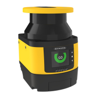
If the display background is white instead of black (and the OSSDs are off) the configuration has been sent to the system but
not accepted.
1.
Inspect nearby areas for lights and retro-reflective surfaces.
• If found, attempt to remove, cover, or otherwise prevent the item from being located in the scanner's detection
plane.
• If you are unable to do this, ensure the appropriate distance has been added to the separation distance (see Z
amb
light factors in Minimum Safety (Separation) Distance Formula on p. 35).
2. Inspect the installation for unmonitored areas and adjacent scanners.
3. In Run mode, observe the scanner's status display to determine status. If any other indication is shown on the
display, see Diagnostic Notes, Warnings, and Errors on p. 105.
4. Ensure that the scanner is in the Run mode, the Safety and Warning Zones are clear of intrusions, and the scanner's
display shows the Zones are clear (or clear and waiting for a reset).
5. Perform a Trip Test to verify the Safety and Warning Zones.
5.3 Perform a Trip Test
Performing a trip test verifies the Safety and Warning Zone fields.
CAUTION: Ensure that no individuals are exposed to any hazard while verifying the Safety and Warning
Zones.
Note: Although the GUI can assist in monitoring the position of objects and the status of the Safety and
Warning Zones, use the display, when possible, to determine whether or not a zone has been interrupted.
1. Ensure that the SX system is in Run mode, the Safety and Warning Zones are clear of intrusions, and the display
shows one of the following:
Zones are clear; OSSDs are on Zones are clear; waiting for a reset input
2. If a Warning Zone is used and with the guarded machine at rest:
a)
Use a test piece that matches the resolution selected for the scanner to interrupt the Warning Zone perimeter.
b) Verify the display shows the yellow warning indication.
c) Remove the test piece and verify the warning indicator returns to the status shown in step 1.
d) Repeat this test along the entire Warning Zone perimeter, paying special attention to needle- and cone-shaped
areas.
Yellow warning indication
3. Use the test piece to interrupt the perimeter of the Safety Zone.
The display when a test piece interrupts the Safety Zone
4. Remove the test piece and verify the display returns to the green Go display shown in step 1.
5.
Repeat this test along the entire Safety Zone perimeter and verify that the configured zone:
SX Safety Laser Scanner
www.bannerengineering.com - Tel: + 1 888 373 6767 65

 Loading...