INSTALLATION GUIDELINES
33
sealing-plug can only be removed with the help of a special tool (according to EN 60079-0, point,
16.4).
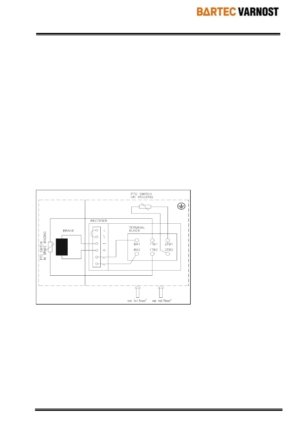
The spring loaded brake type 4BM 71-132 has own terminal box for making connections. Terminal
box cover must be removed to allow individual cable strands of supply cable to be connected to
terminals on terminal board - the customer-specific cable wire strands must be connected to the
terminal board by means of cable shoes.
When fixing the terminal box cover back tightning torque of 7.9 Nm should be applied to screws.
Please note that this operation requires additional knowledge of explosion protection.
The AC supply voltage is rectified by means of built-in rectifier. Brake coil is a DC operated system.
Permanent voltage variation on power source of electromagnetic brake must be limited to ±10%
voltage variation of rated voltage.
Spring loaded brake type 4BM 71-132 are equiped with two PTO thermo switches with switching
temperature corresponding to temperature class or surface temperature designation of explosion
protection.This safety switches must be integrated into control circuit of motor. Termo switches
interrupt the control circuit as soon as temperature exceeds the maximum permitted temperature.
Connection diagram:
6. PROTECTION OF THE ELECTRIC MOTORS AND OPERATION
Succeeding the installation of the electric motors, all rotating parts must be safely protected against
contacts.
Only qualified personnel may handle the machines!
In the S1-mode of operation, the motor circuit-breaker is a sufficient device for the maintenance of
the temperature class. To do so, it must be regulated to the rated current of the three-phase cage
motor.
In both the S2- and S3- modes of operation and the converter operation, the three-phase cage
motors must be equipped with 3 PTCs in each winding (DIN 44080, DIN 44081, DIN 44082). The
nominal shutdown temperature of these PTCs are 145
o
C. A corresponding shutdown device with
 Loading...