Pagina N°.
Page Nr.
Edizione
Edition
S.p.A
11-93
28
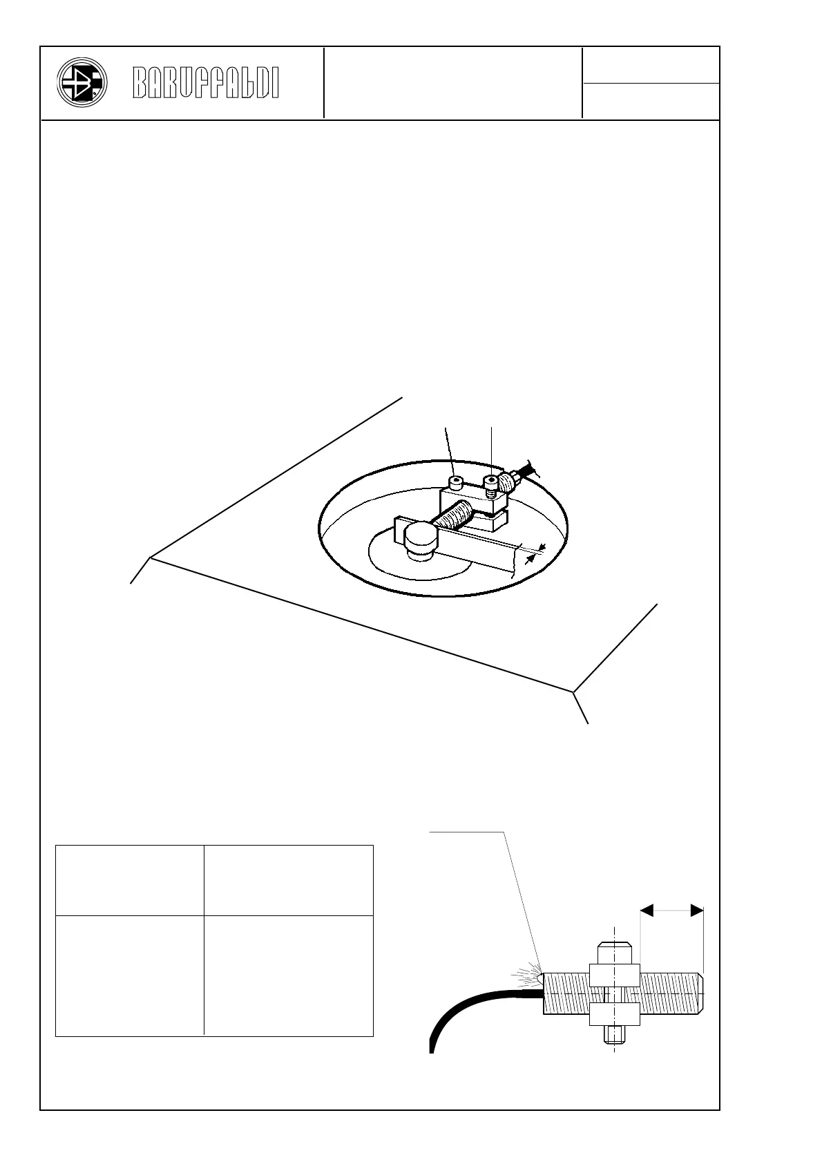
TOEM 120
TOEM 160
TOEM 200
TOEM 250
18,3
18,3
18,3
18,3
X
Luminous indicator
Remove the top cover 044, remove the support 042 together with the proximity switch 301. Remove the rear cover
011, disconnect the proximity switch leads from the terminal block 310, and remove the proximity switch. Screw
the new proximity switch into the support until it projects by the correct amount "X".
Assemble the support fixing it with the screw 300a in such a way that the LED (luminous indicator) on the end of
the proximity switch is visible. Insert a 0,8 mm thickness gauge (see figure) and bring the proximity switch into
contact with the thickness gauge.
Tighten the screws 300 - 300a with a torque of 3 Nm and block them with LOCTITE.
Connect the leads to the terminal block, and check that the proximity switch operates correctly when live, as follows:
- With a turret closed (locked) on lowering the end of the electromagnet by an amount between 1,8 and 2,5 mm the
luminous "red" indicator on the back part of the proximity switch should light up.
Replace the rear cover and the top cover.
300 a
300
0,8
SUBSTITUTION &
ADJUSTEMENT OF THE
PRE-INDEXING PROXIMITY SW.
X
(mm)
Turret size