4
© 2020. All rights reserved.
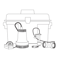
PREPARATION
Estimated Installation Time: 2-4 hours
Materials required for assembly: Deep-cycle marine battery, discharge piping and fittings (PVC,
poly pipe or galvanized steel), ‘Y’ pipe, 1-1/2-in 45° elbow, 1-1/2-in check valve, 1-1/4” MNPT x 1-1/2”
PVC socket adapter and 2-step PVC glue system (primer and sealer).
GENERAL PUMP INFORMATION
SPECIFICATIONS
MODEL
PERFORMANCE IN GALLONS PER MINUTE
0 FT. 5 FT. 10 FT. 14 FT.
STBB100 29 20 10 Shut Off
This pump is designed to be installed in a sump basin along with a primary, 115V sump pump
for removing clear drain water. It is not a substitute for a primary sump pump. It is designed to
temporarily backup the primary sump pump in the event of a power outage or 115V pump failure.
The sump basin must be at least 18-in deep by 14-in diameter.
This system is designed to work with a deep-cycle marine battery, either a ooded lead-acid battery
or a sealed, maintenance-free lead-acid battery. Use of an automobile battery instead of a deep-cycle
marine battery in this system will signi cantly reduce pump performance. Automobile batteries are not
designed for this type of application and will not stand up to repeated charge and discharge cycling.
Both the primary pump and DC backup pumps will require check valves in the discharge pipes for
proper operation.
NOTE: Pump must be submerged in water before operation. Running the pump dry will cause
damage and void the warranty.
NOTE: The alarm will sound after connecting the battery. It will continue to sound until all
connections are made and the oat switch is in the down position.
The pump will continue to run for an additional 10 seconds after the float has been lowered. The
alarm will continue to sound while the pump is working.
Place the battery in a cool, dry, well-ventilated area on a shelf or protective plywood board. If a carbon
monoxide (CO detector) is installed in the same area as the DC pump system, it must be at least
15 ft. away from the battery in order to avoid nuisance CO alarms. Refer to CO detector installation
guidelines for more information.
5
© 2020. All rights reserved.
INSTALLATION INSTRUCTIONS
NOTE: Install the battery backup system when the
primary pump is not needed. Read instructions and
prepare all supplies before beginning installation.
1. Verify that the existing 115V sump pump is in
good working order. It is best to use a primary
sump pump with a vertical oat switch. Pumps
with tethered oat switches require more space
and may interfere with the operation of the
backup sump pump switch.
1
2. Manually operate the primary sump pump to
remove as much water as possible from the
basin. Do not let the pump run dry.
3. Disconnect the primary sump pump from power
source before installing the DC pump.
WARNING: Never handle a pump with wet
hands or when standing on wet or damp
surface or in water. Fatal electrical shock
could occur.
 Loading...