BASEWEST
Operating & Maintenance Manual
Model TS-420 Test Set
Page 4 of 10 25-60-41
24 Jan 2002
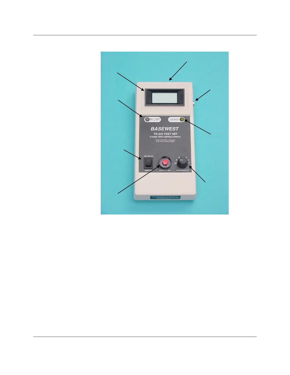
Figure 2. TS-420 – General Arrangement
3.0 Battery Testing (Voltmeter Mode)
3.1 Move the Mode Selector switch to VOLTMETER.
3.2 Connect the 4-contact test lead on the battery pack to the mating receptacle on the
connector block of the instrument (See Figure 3). Note that the connector is keyed for
proper alignment.
3.3 Select the proper test load (NO LOAD, or positions A through F) on the Load Selector
switch. Refer to OEM manuals for correct test load setting. The NO LOAD position
provides an open circuit test of the battery pack.
3.4 Press-To-Test; record voltage of the battery pack under the selected condition. The Self-
Test indicator must illuminate GREEN at this point. If not, see Section 6.0
3.5 Release the Press-To-Test switch when the voltage is recorded. The test set will return to
the OFF condition. NOTE: This test can also be accomplished by connecting one set of
the battery power lead connectors to the VOLTMETER inputs on the connector block (see
Figure 3).
Self Test Indicator
(Green / Red LED)
Battery Status Indicator
(Amber LED)
Mode Selector Switch
(Voltmeter/Ammeter)
Connector Block
(See Fig 3)
 Loading...