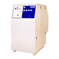
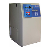
ImVT 120 II Mini Verticus
Page 46 1st Edition, Rev. 0 Chg. 10
3.2.1.1 Normal Operation
The normally open solenoid valve (1) controls the condensate draining of the intermediate separator
(2). The normally open condensate drain valve (4) controls the condensate draining of the oil and water
separator. The two valves (1 & 4) are connected together in cascade mode. This means that the opera-
tional state (open or closed) of the solenoid valve (1) causes the same state in the condensate drain
valve (4) to occur. The control air for operating the condensate drain valve (4) is taken from the inter-
mediate separator (2).
As the compressor is started, the solenoid valve (1) is electrically energized and closes. This allows the
pressure to buildup in the intermediate separator. This pressure buildup results in control air pressing
the piston into the valve seat, closing the condensate drain valve (4).
3.2.1.2 Condensate Drain
Every 15 minutes the timer deenergizes the solenoid valve (1) for approximately 10 seconds. The sole-
noid valve (1) opens and drains the condensation from the intermediate separator (2). This causes a
pressure loss in the intermediate separator and the control air for the condensate drain valve (4). As the
pressure of the control air is dropping, the piston of the condensate drain valve (4) becomes unloaded
and the control air is momentarily vented through a relief port. Then the piston of the drain valve is
fully raised by pressure from the final separator, and the condensate is drained.
3.2.1.3 Start Unloading
The unloading of the compressor during the starting phase is possible because of the lack of control air
immediately after starting the unit. As the unit is switched on the solenoid valve (1) is energized and
Figure 3-32 ACD Operation Diagrams
1. Solenoid Valve
2. Intermediate Separator
3. Oil and Water Separator
4. Condensate Drain Valve
Normal Operation
Condensate Draining
Condensate
Control Air
2
1
4
Condensate
Control Air
2
1
3
4
3
 Loading...