ImVT 120 II Mini Verticus
Page 76 1st Edition, Rev. 0 Chg. 10
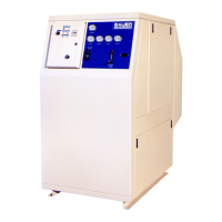
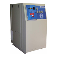
7.4.5 Compressor Control Switches
7.4.5.1 2-Position (Standard)
OFF Position - The selector switch must be in the OFF position when securing the compressor system.
ON Position - The selector switch must be in the ON position to operate the compressor system. When
positioning the switch to the ON position, it will illuminate Green. The compressor will start and stop
automatically based on the status of the pressure switch.
7.4.5.2 3-Position Compressor Control Switch (Factory Installed Option).
7.4.5.2.1 For Breathing Air Units
OFF - The selector switch must be in the OFF position when securing the compressor system.
ON - The selector switch must be in the ON position to operate the compressor system. When position-
ing the switch to the ON position, it will illuminate Green. The compressor will start and stop automat-
ically based on the status of the pressure switch.
ACD Test - This switch position will cause all condensate drains to blow down. It is spring returned to
ON Position when released.
7.4.5.2.2 For Industrial Units
OFF - The selector switch must be in the OFF position when securing the compressor system.
AUTO- The selector switch must be in the ON position to operate the compressor system. When posi-
tioning the switch to the ON position, it will illuminate Green. The compressor will start and stop auto-
matically based on the status of the pressure switch.
CONTINUOUS - This switch position, maintained, will allow the compressor to build up to final pres-
sure, then will activate an unloading valve. When demand is re-established, the unloading valve is de-
energized and compression will begin again.
7.4.6 Indicator Lamps
7.4.6.1 PLC Warning and Alarm Lamps
7.4.6.1.1 Warning Lamp - Amber
The lamp (LIT-0128) has a 22 mm base and a LED lamp for long trouble free life. This lamp should
flash a code IAW, In Accordance With, the logic of the controller. See Paragraph 7.5.
7.4.6.1.2 Alarm Lamp - Red
The lamp (LIT-0127) has a 22 mm base and a LED lamp for long trouble free life. This lamp should
flash a code IAW the logic of the controller. See Paragraph 7.6.
7.4.7 Hour meter
The panel will be supplied with an hour meter (HMR-0029). The hour meter is not resettable and used
to monitor the run hours of the compressor. It is powered with a 120 VAC signal supplied from the aux-
iliary contact on the motor starter.
7.4.8 PLC Control
This panel is controlled with a Telemecanique 16 I/O Twido Programmable Logic Controller. This unit
provides logical operations to the overall system that includes the high pressure compressor, purifica-
tion systems, and other accessories.
 Loading...