EasyManua.ls Logo

Baumer FPCK 07P6901/KS35A - User Manual

Baumer FPCK 07P6901/KS35A
2 pages
Print Icon
To Next Page IconTo Next Page
Loading...
FPCK 07P6901/KS35A
10151062
Í?*/*^ÂÂ*Â-Î
1/2
Optoelektronische Sensoren
Photo electric sensors
Cellules opto-électroniques
Reflexions-Lichtschranke
mit Polarisationsfilter
Retro-reflective sensor
with polarization filter
Barrière réflex avec
filtres de polarisation
Canada
Baumer Inc.
CA-Burlington, ON L7M 4B9
Phone +1 (1)905 335-8444
China
Baumer (China) Co., Ltd.
CN-201612 Shanghai
Phone +86 (0)21 6768 7095
Denmark
Baumer A/S
DK-8210 Aarhus V
Phone: +45 (0)8931 7611
France
Baumer SAS
FR-74250 Fillinges
Phone +33 (0)450 392 466
Germany
Baumer GmbH
DE-61169 Friedberg
Phone +49 (0)6031 60 07 0
India
Baumer India Private Limited
IN-411058 Pune
Phone +91 20 66292400
Italy
Baumer Italia S.r.l.
IT-20090 Assago, MI
Phone +39 (0)2 45 70 60 65
Singapore
Baumer (Singapore) Pte. Ltd.
SG-339412 Singapore
Phone +65 6396 4131
Sweden
Baumer A/S
SE-56133 Huskvarna
Phone +46 (0)36 13 94 30
Switzerland
Baumer Electric AG
CH-8501 Frauenfeld
Phone +41 (0)52 728 1313
United Kingdom
Baumer Ltd.
GB-Watchfield, Swindon, SN6 8TZ
Phone +44 (0)1793 783 839
USA
Baumer Ltd.
US-Southington, CT 06489
Phone +1 (1)860 621-2121
www.baumer.com/worldwide
Baumer Electric AG · CH-8501 Frauenfeld
Phone +41 (0)52 728 1122 · Fax +41 (0)52 728 1144
Abmessungen
Dimensions
Dimensions
7,56,2
ø 5,2
LED
Teach-in
9,2
3
18
23,5
21,4
12,4
15,4
13,4
3
,
2
2
x
ø
10,7
3
ø
1,58,25
9,3
6 *4
8
12,6
6,4
17,8
Alle Masse in mm
• All dimensions in mm
Toutes les dimensions en mm
* Senderachse
* Emitter axis
* Axe de l'émetteur
Elektrischer Anschluss
Connection diagram
Schéma de raccordement
0 V
PNP
WH (2)
BU (3)
BN (1)
BK (4)
Z
+VS
light/dark
ext. teach
BN = Braun/brown/brun
BK = Schwarz/black/noir
WH = Weiss/white/blanc
BU = Blau/blue/bleu
•Anschlussleitung nicht unter Zug verlegen.
•Do not install the cable under tension.
•Eviter tout effort de traction sur le câble de raccordement lors de sa pose.
• Vor dem Anschliessen des Sensors die Anlage spannungsfrei schalten.
• Disconnect power before connecting the sensor.
• Mettre l`installation hors tension avant le raccordement du détecteur.
Technische Daten
Technical data
Données techniques
Betriebsspannungsbereich Vs (UL-Class 2) Voltage supply range Vs (UL-Class 2) Plage de tension Vs (UL-Class 2)
max. Stromverbrauch Mit tel- / Spitzenwert max. supply current average / peak Consommation moyenne / pointe max.
max. Schaltstrom max. switching current Courant de sortie
max.
Spannungsabfall Voltage drop Tension résiduelle
Ansprechzeit Response time Temps d'activation
Abfallzeit Release time Temps désactivation
Kurzschlussfest Short circuit protection Protégé contre courts-circuits
Verpolungsfest Reverse polarity protection Protégé contre inversion de polarité
Betriebstemperatur Temperature range Température de service
Schutzklasse Protection class Classe de protection
max. Anzugsdrehmoment max. tightening torque Couple max. de serrage
Grenzreichweite Sn Nominal range Sn Limite de portée Sn
Betriebsreichweite Sb Actual range Sb Portée de fonctionnement Sb
10 - 30 VDC
20 mA / 25 mA
100 mA
1,8 VDC
0,5 ms
0,5 ms
ja / yes / oui
ja / yes / oui
-20...+50 °C
IP 65
0,35 Nm
600 mm
500 mm
Technische Änderungen vorbehalten Technical specifications subject to change Sous réserve de modifications techniques
Question and Answer IconNeed help?

Do you have a question about the Baumer FPCK 07P6901/KS35A and is the answer not in the manual?

Overview

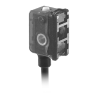
The FPCK 07P6901/KS35A is a retro-reflective sensor with a polarization filter, designed for optoelectronic sensing applications. It is manufactured by Baumer Electric AG.

Function Description

This sensor operates on the principle of retro-reflection, utilizing a polarization filter to enhance detection reliability. It emits a light beam, which is reflected by a suitable reflector and then detected by the sensor. The polarization filter helps to suppress reflections from shiny objects that are not the intended reflector, thereby improving the accuracy and stability of detection.

The device features a Teach-in function, allowing for flexible configuration to suit various application requirements. This can be performed either statically for non-moving objects or dynamically for moving or small objects. The Teach-in process involves guiding the sensor through the desired ON and OFF positions, or by sensing minimum and maximum values during dynamic operation. Feedback on the Teach-in process is provided via a green LED, indicating successful configuration or warning of potential issues such as insufficient signal difference or operation outside the sensing range.

The sensor offers both light-operate and dark-operate output functions, which can be selected during the Teach-in process. The output function can be switched from light-operate (standard) to dark-operate by a specific button press sequence after the Teach-in procedure.

Important Technical Specifications

  • Nominal Range (Sn): 600 mm
  • Actual Range (Sb): 500 mm
  • Voltage Supply Range (Vs): 10 - 30 VDC (UL-Class 2)
  • Max. Supply Current (average/peak): 20 mA / 25 mA
  • Max. Switching Current: 100 mA
  • Voltage Drop: ≤ 1.8 VDC
  • Response Time: ≤ 0.5 ms
  • Release Time: ≤ 0.5 ms
  • Short Circuit Protection: Yes
  • Reverse Polarity Protection: Yes
  • Temperature Range: -20 to +50 °C
  • Protection Class: IP 65
  • Max. Tightening Torque: 0.35 Nm
  • Dimensions: The sensor has a compact design with a main body measuring approximately 23.5 mm in length, 18 mm in width, and 13.4 mm in height. It features mounting holes with a diameter of 3.2 mm.

Usage Features

Teach-in Procedures:

  • Static Teach-in (for non-moving parts):

    1. Enter static Teach-in mode by pressing the button for approximately 2 seconds until the green LED flashes.
    2. Position the object in the desired ON-position and briefly press the button.
    3. Position the object in the desired OFF-position and briefly press the button.
    4. The sensor's output is set to dark-operate if the order of ON and OFF positions is interchanged; otherwise, it's set to light-operate.
  • Dynamic Teach-in (for moving and small objects):

    1. Enter dynamic Teach-in mode by pressing the button for approximately 5 seconds until the green LED's flashing changes from slow to fast. Upon releasing the button, the sensor immediately begins to sense minimum and maximum values.
    2. Stop the Teach-in procedure by briefly pressing the button.
    3. To change the output function from light-operate (standard) to dark-operate, briefly press the button again within 5 seconds after stopping the Teach-in procedure.
  • External Teach-in: The Teach-in process can also be initiated externally by connecting the Teach-in input to +Vs (for PNP) or 0V (for NPN).

Teach-in Feedback:

  • Teach-in OK: Green LED lights up for 2 seconds, indicating successful configuration within the sensing range and with sufficient signal difference.
  • Teach-in Warning: Green LED flashes for 2 seconds, indicating insufficient signal difference for a safe application or that the sensor was taught beyond its sensing range.

Troubleshooting/Indicators:

  • A flashing green LED indicates insufficient signal reserve, that the sensor is in Teach-in mode, or a Teach-in warning due to insufficient signal difference.
  • The yellow LED indicates the output status.
  • The green LED indicates excess gain or serves as an alignment aid/soiled lens indicator when flashing.

Maintenance Features

  • Electromagnetic Compatibility: To enhance immunity against electromagnetic interference, it is recommended to install the sensor with the provided insulation plate.
  • Connection: Always disconnect power before connecting the sensor. Avoid installing the cable under tension or applying any pulling force to the cable during installation.
  • ESD Precautions: Proper ESD precautions should be taken during installation and commissioning. As a minimum ESD protection measure, it is recommended to touch the metal frame to which the sensor is mounted before teaching the sensor.
  • Cleaning: The manual does not explicitly detail cleaning procedures, but given the "soiled lens indicator" function, it implies that keeping the lens clean is important for optimal performance. Regular inspection for dirt or obstructions on the lens is advisable.

Baumer FPCK 07P6901/KS35A Specifications

General IconGeneral
BrandBaumer
ModelFPCK 07P6901/KS35A
CategorySecurity Sensors
LanguageEnglish