PAGE 27 TP10313
1.3 FRONT BLOW TUBE SETTINGS
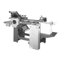
The front blow consists of two tubes (Figure 13-1 & 2
and Figure 15-1 & 2) instead of the traditional one tube.
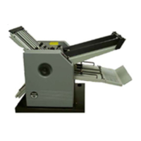
The numbers on the left hand side of the tubes correspond to
the chart (Figure 15-3) found on the side of the main control
enclosure.
Setting Up
1.) Determine the width of the job to be run.
2.) Find the numbers on the right-hand side of chart
that correspond with the sheet width.
3.) Set the top (15-1) and bottom (15-2) blow tubes,
using the detent slots, to the respective numbers.
Vacuum adjustment is made at the pump (Figure 16)
using the valve (16-1). Vacuum adjustment requirements
should be minimal. Listen to the feeding at the vacuum
wheel to determine if there is too much vacuum. The
vacuum valve (16-1) should be set as shown for most
applications.
1.4 Vacuum Wheel
The vacuum flow is controlled by a solenoid valve
(Figure 11-4 & 17-1). This can be quickly and easily
removed to clean the piston (17-2) by releasing the clamp-
ing springs. Be careful not to damage the piston and
cylinder.
The vacuum wheel (Figure 18-1) is supplied with two
O-rings (18-2) to assist feeding with a positive friction grip.
These O-rings are replaced after removing the guard (18-3)
by removing the two button head screws (18-4) holding it.
Figure 16
Figure 17
Figure 15