HB-37350-810-01-51F-EN SMX Installation manual.docx Page 105 of 234
Version: 50F
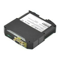
5.2 Installation and assembly of the SMX module
The module is solely to be installed in control cabinets with a degree of protection of at least
IP54.
Only cULus:
This device is intended to be used indoor only.
The modules must be vertically fastened on a top hat rail
The ventilation slots must be kept unobstructed, to ensure adequate air circulation inside the
module.
For air vents, there must be free space of 30 mm above and below the vents. Stringing of
expansion modules is permitted. As the adjacent devices can generate waste heat, a distance of
20 mm should be maintained.
Note:
When using in non-closed spaces, it must be guaranteed that the environmental conditions of
the individual modules (see technical data) are adhered to.
5.3 Installation of backplane bus system
Mounting several SMX modules (SMX10/10A/10R/10AR, SMX11, SMX11-2, SMX12/12A,
SMX12-2/12-2A) on one top hat rail in connection with the backplane bus system is also
possible. These modules can be combined with a communication extension. In this case the
backplane bus system needs to be configured by BBH when placing the order and delivered in
accordance with the application in question.
The backplane bus system consists of a 5-pin plug connector with snap-in contacts. In these
plug connectors all 5 contacts are equipped by standard. In this case the component is not
specially marked. On a second variant of the plug connector only 3 contacts are equipped.
Note:
Expansion modules have no own power supply unit and depend on a DC power supply via the
backplane bus system. Base modules (SMX10/11/12) are equipped with a reinforced power
supply unit and always feed in to the backplane bus.
There are two different types of backplane bus connectors:
• TB1: Standard design (all contacts are present)
• TB2: Circuit breaker design (The two live conductors are not present and are marked
with a green dot.
Using the backplane bus connector TB1:
The backplane bus connector TB1 can only be installed in connection with expansion modules
without their own power supply. Connection of several standalone modules is not possible.
 Loading...