HB-37350-810-01-51F-EN SMX Installation manual.docx Page 27 of 234
Version: 50F
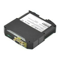
3.2.1.3 SMX11-2(/2, /4x, /x
(1)
)
Design of module with the following periphery:
1 Axes
5 Encoder interfaces
14 Digital Inputs
2 Pulse outputs
2 Relay outputs
2/4 pn- or pp- switching outputs
2 Auxiliary outputs
1 Diagnostic and configuration interface
1 Function button
1 7-segment display
1 status-LED
14 status LEDs for inputs
2 status-LEDs für Pulse outputs
2 status-LEDs für Relay outputs
6 status LEDs for outputs
1 Optional: Communication interface (/4x, 5x, /x
(1)
)
Characteristics of the module:
• Extendable to:
o max. 42 safe digital inputs,
o max. 12 safe digital outputs,
o max. 20 sichere digitale I/O’s,
o max. 9 safe relay outputs,
o max. 10 auxiliary outputs
o max. 1 safe axis
• Logic processing up to PL e acc. to with EN ISO 13849-1 or SIL 3 acc. to with IEC
61508
• Movement monitoring of one or two axes up to Pl e EN ISO 13849-1 or SIL 3 acc. to
IEC 61508
• Speed monitoring:
• RPM-monitoring
• Standstill monitoring
• Sense of rotation monitoring
• Safe incremental dimension
• Emergency Stop monitoring
• Position monitoring
• Position range monitoring
• Trend range monitoring
• Target position monitoring
• Freely programmable Modular controller for up to 800 IL instructions
• Logic diagram oriented programming
• Pulse outputs for cross-shorting detection of digital input signals
• External contact monitoring of connected switchgear (EMU)
 Loading...