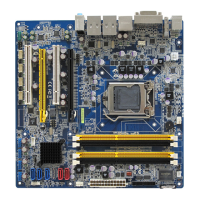
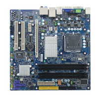
Motherboard Layout:
WARNING: Electrostatic Sensitive Device (ESD)
Static electricity can easily damage your motherboard and will void your motherboard
warranty. Keep the motherboard and other system components in their anti-static
packaging until you are ready to install them. Touch a grounded surface before you
remove any system component from its protective anti-static packaging. Unpacking and
installation should be done on a grounded, anti-static mat. The operator should be wearing
an anti-static wristband, grounded at the same points as the anti-static mat. During
configuration and installation touch a grounded surface frequently to discharge any static
electrical charge that may have built up in your body. Avoid touching the components
when handling the motherboard or a peripheral card. Handle the motherboard and
peripheral cards either by the edges or by the peripheral card case-mounting bracket.
WARNING: Misplaced Jumper Damage
Incorrect setting jumpers and connectors may lead to damage to your motherboard and will
void your motherboard warranty. Please pay special attention not to connect these
headers in wrong directions. DO NOT change ANY jumpers while the motherboard has the
power!
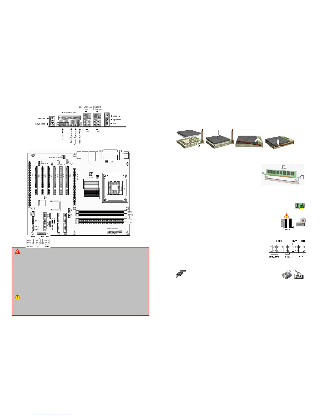
Install a CPU:
Please follow the below steps to install your CPU in
SOCKET 478
.
Step 1: Pull the handling bar of the socket upward to the other end to loosen the socket’s
openings.
Step 2: Place the CPU on the middle of the socket, orienting its beveled corner to line up
with the socket’s beveled corner. Make sure the pins of the CPU fit evenly to the
socket openings.
Step 3: Press the handling bar downward to fasten the CPU to the socket.
Step 4: Install the CPU heatsink with some thermal jelly on the CPU and secure the
brackets.
Install a DIMM:
Step1:
Make sure
Pin 1 of the DIMM match
with pin 1
of the
DIMM 0
, and
DIMM 1
sockets.
Step2:
Insert the DIMM module into the DIMM socket
vertically. After inserting the DIMM module
completely into the socket, push up on the
socket latches securing the DIMM into place.
If the pin 1 of the DIMM module does not line
up with pin 1 of the socket, the DIMM module will not be inserted correctly into
the socket.
Install a Peripheral Card:
To install expansion cards, please read the expansion card’s documentation for
instructions or cautions prior to the installation.
Install the Drives:
Install the floppy drive cable to
FLOPPY
, the hard disk drive cable to
PRIMARY IDE
, the CD-ROM, DVD-ROM, CD-R, or CD-RW cable to
SECONDARY IDE
.
NOTE: Colors on the IDE ports may vary.
Plugging-In the ATX Power Supply Connector:
Plug the ATX Power Supply cable to
ATX POWER
and
ATX 12V
.
Plugging-In the Front Panel Connectors:
Plug in each cable to their assigned headers as labeled on
the connectors (
FRONT PANEL CONNECTORS
) and the
figure on the right. If the light does not lit up, simply reverse
the polarity. The colored wires of each connector usually
denote a positive lead, which aligns with red arrows as
illustrated on the right.
Plugging-In the Back Panel Ports:
Plug in Keyboard, Mouse, USB, Serial 1 (COM1), LAN, Video
and Parallel (printer) ports. Please refer to the figure on the
Motherboard Layout page.
Jumpers:
The BIOS handles all of the configurations including FSB speed, and CPU multiplier.
Other Connectors:
CPU fan connector needs to be connected to the
CPU FAN
if the heatsink is equipped with
one. System fan connector needs to be connected to the
SYS FAN
if the system is
equipped with one. Case fan connector needs to be connected to the
CASE FAN
if the
case is equipped with one.
 Loading...