Page 3
Single Electric Fan Wiring Harness with Temperature Sending Unit and 40 Amp Waterproof Relay
Be Cool Part Numbers:
#75098 - Temperature Sending Unit Turns Fan on at 210˚, off at 190˚
#75021 - Temperature Sending Unit Turns Fan on at 195˚, off at 175˚
#75032 - Temperature Sending Unit Turns Fan on at 185˚, off at 165˚
#75017 - Wiring Kit with no Temperature Sending Unit
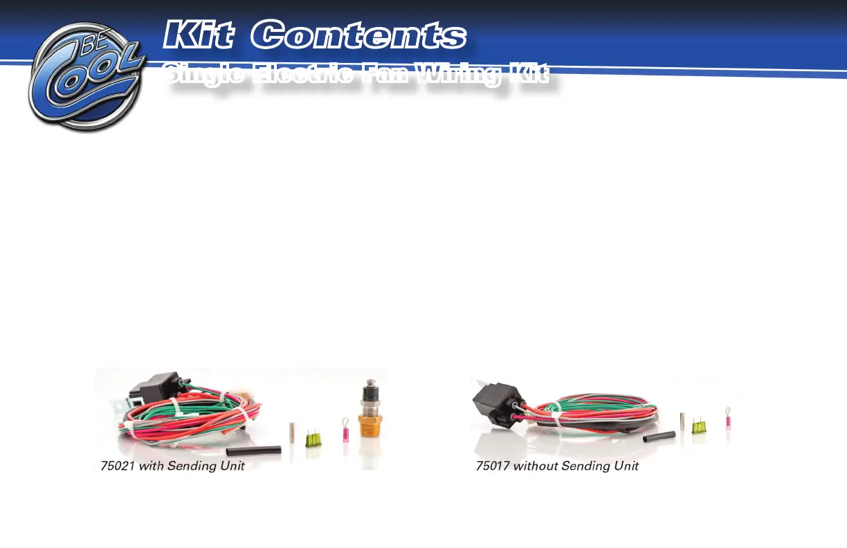
Kit Contents for #75017, #75021, #75032, or #75098:
• Harness with Relay, Socket, and Fuse Holder • #75029 Temperature Sending Unit (for kit #75032)
• #75030 Temperature Sending Unit (for kit #75021) • #75099 Temperature Sending Unit (for kit #75098)
• Butt and Eyelet Connectors • Shrink Tubing
See page 5 for installation instructions and pages 6 & 7 for wiring diagrams for
vehicles without air conditioning and pages 8 & 9 for vehicles with air conditioning.
Page 18
Toggle
Switch
Wiring
Diagram
Wiring Diagram
for Be Cool Kit
Part Number:
#75096 Toggle Switch
Page 16
DISCONNECT BATTERY before any mechanical or electrical installation.
Mount the relay in a dry position on the vehicle. When this is completed, connect the wires as per the diagram.
Wiring Instructions for Be Cool Kit Part #75196 (Follow all instructions)
Red Wire:
Plug the red and black wires (with white plastic plug) from the relay to the white plastic plug on the fan har-
ness.
Gray Wire: Connect the gray wire from the relay to the temperature sending unit using the enclosed eyelet connector.
Orange Wire/Fuse: Connect the eyelet end on the fuse holder assembly to the positive battery terminal.
Green Wire: Connect the green wire from the relay to the ignition terminal in fuse box.
Wiring Instructions for Be Cool Kit Part #75096
Gray Wire: Connect the gray wire from the relay to the temperature sending unit using the enclosed butt connector.
Black Wire: Connect the black wire to the eyelet connector and then to the chassis ground.
Instructions:
Connect a high amp toggle switch (Be Cool Kit #75096) to the temperature sending unit’s gray wire. This will
close the circuit when the switch (SPST; Single Pole, Single Throw) is on.
Page 5
DISCONNECT BATTERY before any mechanical or electrical installation.
Mount the relay in a dry position on the vehicle. When this is completed, connect the wires as per the diagram.
Red Wire:
Plug the red and black wires (with white plastic plug) from the relay to the white plastic plug on the fan har-
ness.
Gray Wire: Connect the gray wire from the relay to the temperature sending unit using the enclosed eyelet connector.
Orange Wire/Fuse: Connect the eyelet end on the fuse holder assembly to the positive battery terminal.
Green Wire: Connect the green wire from the relay to the ignition terminal in fuse box.
For air conditioned vehicles, use Be Cool Kit #75095. When air conditioning is activated, fans will turn on regardless of engine
temperature.
Wiring Instructions for Optional A/C Wiring Harness Kit Be Cool Part #75095
Blue Wire: Connect the blue wire to the blue wire on the A/C compressor power input with butt connector.
Gray Wire: Connect the gray wire from the relay to the temperature sending unit using the enclosed eyelet connector.
Black Wire: Connect the black wire to the eyelet connector, and then to the chassis ground.
Optional ---------->
Connect a high amp toggle switch (Be Cool Kit #75096) to the temperature sending unit’s gray wire. This will
close the circuit when the switch (SPST; Single Pole, Single Throw) is on.
Kit Contents
Single Electric Fan Wiring Kit
See page 5 for installation instructions, pages 6 & 7 for wiring diagrams for
vehicles without air conditioning, and pages 8 & 9 for vehicles with air conditioning.
115304 BeCool Wiring Harness Text.indd 1 1/11/19 11:03 AM
 Loading...