STEP I - MOUNTING PREPARATION
POWER MUST BE OFF.
(WIRING MUST BE PERFORMED BY A QUALIFIED ELECTRICIAN)
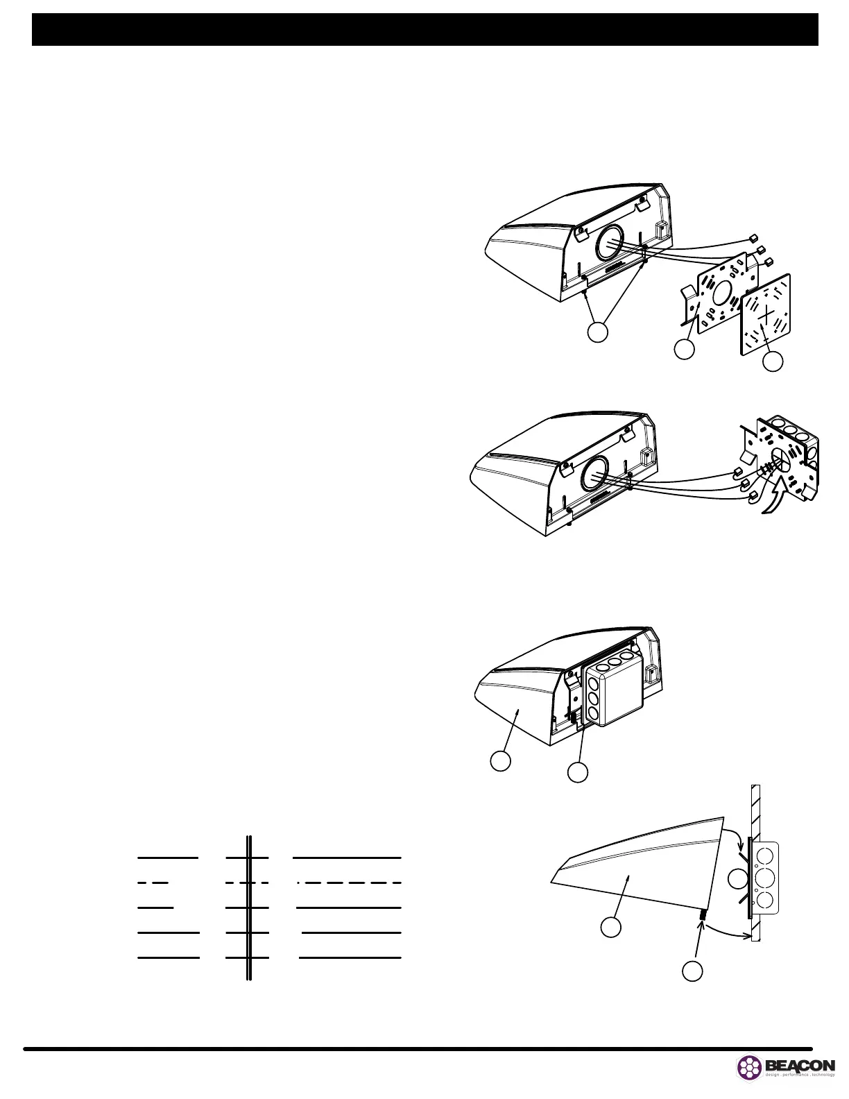
Remove fixture mounting bracket (A) from fixture by loosening the hex set
screws (B).
Remove paper backing from gasket (C) and apply to mounting bracket (A)
on the side shown. (See FIG.1)
Align holes in bracket to your matching j-box holes.
Secure and level mounting bracket to the j-box.
If no junction box is available, mounting plate must be securely anchored to
wall with appropriate hardware (not provided).
Apply a bead of silicone caulk (not provided) around the top and two sides
of the bracket where it meets the wall.
STEP II WIRING
Connect service leads to fixture power leads according to local and National
Electric Codes. (See FIG.5)
For direct wire connections, connect ground wire to the green wire.
Connect black to line and white to neutral then push connections back
inside j-box (See FIG.2)
STEP III FIXTURE MOUNTING
Hold fixture (D) at slight angle as shown (FIG.4), align, lower, and rotate
over mounting bracket (A) until fixture sits flat against wall.
Tighten the two (2) set screws (B) securely to capture the mounting
bracket (A).
Check to ensure the fixture is securely mounted.
Energize product.
BATTERY BACK-UP (BBU) INFORMATION
FOR UNITS EQUIPPED WITH BBU:
Must be charged for 24 hours before use. *Once A/C power is supplied to
fixture, emergency BBU will remain active, even if A/C power is removed.
BBU units are only equipped for 120V or 277V input.
Maximum mounting height: 23.8 ft.
IMPORTANT SAFEGUARDS
READ AND FOLLOW ALL SAFETY INSTRUCTIONS.
Do not mount near gas or electric heaters.
Equipment should be mounted in locations and at heights where it will not
readily be subjected to tampering by unauthorized personnel.
The use of accessory equipment not recommended by the manufacturer
may cause an unsafe condition.
Do not use this equipment for other than intended use.
•
•
•
•
•
•
•
•
•
•
•
•
•
•
•
•
•
•
•
•
•
•
www.beaconproducts.com
701 Millennium Boulevard Greenville, SC 29607 (864) 678-1000
C
A
B
ONCE ALL CONNECTIONS ARE
MADE, PUSH ALL CONNECTORS
AND EXCESS WIRING INSIDE J-BOX
A
D
A
D
B
FIGURE 4
FIGURE 3
FIGURE 2
FIGURE 1
INSTALLATION INSTRUCTIONS - VIPER WALL SIZES 1, 2, AND 3 SHEET 2 OF 4
FIGURE 5
OUTSIDE
FIXTURE
INSIDE
FIXTURE
LINE
BLK
WHT
COMMON
GROUND
GRN
PUR
DIM +
PNK
DIM -
BUILDING
CONNECTION
95062889 Rev A
READ AND FOLLOW ALL
SAFETY INSTRUCTIONS.
SAVE THESE INSTRUCTIONS.
 Loading...