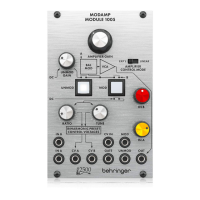
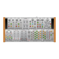
1. FILTER - Adjusts the cutoff
frequency of the filter.!
2. FILTER RESONANCE - Boosts the
resonance frequencies selected with
the Filter knob, potentially causing
VCF oscillation. !
3. AMPLIFIER GAIN - Controls the
level of the VCA.!
4. KEYBOARD knob - Attenuate the
voltage connected to the KYBD
input, which controls the cutoff
frequency of the filter. !
5. IN B knob - Adjusts the level of the
signal connected to the IN B input.!
6. CV 2 to VCF knob - Attenuate the
voltage that is passed from the CV 2
input to the VCF.!
7. IN A knob - Adjusts the level of the
signal connected to the IN A input.!
8. CV 1 to VCF knob - Attenuate the
voltage that is passed from the CV 1
input to the VCF.!
9. EXPONENTIAL/LINEAR switch -
Select between a linear or more
natural exponential VCA response.!
10. CV 2 to VCA knob - Attenuate the
voltage that is passed from the CV 2
input to the VCA.!
11. CV 1 to VCA knob - Attenuate the
voltage that is passed from the CV 1
input to the VCA.!
Patchpoints!
12. IN A - Connect an input signal via
3.5 mm TS cable.!
13. IN B - Connect an input signal via
3.5 mm TS cable.!
14. KYBD - Connect a voltage that can
be used to control the VCF
frequency.!
15. CV 1 - Connect a voltage that can be
used to control the VCF frequency or
VCA level.!
16. CV 2 - Connect a voltage that can be
used to control the VCF frequency or
VCA level.!
17. OUT - Send the processed signal to
other modules via 3.5 mm TS cable.