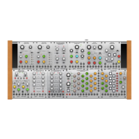
1. CH A / CH B / CH C SEQUENTIAL
COLUMNS - Use the knobs to set the
control voltage output for each step. Each
column sends out control voltages via
that channel’s respective CH A / CH B /
CH C output jack.!
2. STEP LEDs - Each LED lights to indicate
its respective sequencer step is active. !
3. POSITION GATES - Each of these output
jacks sends out a gate signal for its
respective sequence step via cables with
3.5 mm TS connectors. These 8 gate
outputs signals are also available via the
12-pin GATE OUT LINK CONNECTOR
located on the modules underside. This
12-pin connector cab connect to and
trigger other compatible modules, such
as the MIX-SEQUENCER MODULE 1050,
via a 12-pin ribbon connector.!
4. RATE - This knob controls the step speed
at which the sequencer moves from step
to step. The knob operates in two overall
frequency ranges determined by the
LOW/HIGH switch.!
5. LOW/HIGH - Use this sliding switch to
set whether the RATE knob operates in a
lower-frequency (LOW) or higher-
frequency (HIGH) range.!
6. % PULSE WIDTH - Select between
settings for the rectangular waveform
ranging from 5% to 95% duty cycle. The
PULSE WIDTH control operates on the
CLK OUT jack only, making this control
very useful for triggering other modules
such as envelope generators, and so on. !
7. IN/EXT - Use this switch to select
between (INT) or external (EXT) pulse
width control voltage. When EXT is
selected the % PULSE WIDTH control
knob is disabled. !
8. ON/OFF - This button starts or stops the
sequence with a manual button push.!
9. STEP - Press this button to manually
progress to the next sequence step. !
10. RESET - Press this button to manually
restart the sequence at step 1. !
Patchpoints!
11. STEP - Use this jack to route external
trigger signals for the STEP button into
the module via cables with 3.5 mm
TS connectors.!
12. RESET - Use this jack to route external
trigger signals for the RESET button into
the module via cables with 3.5 mm TS
connectors.!
13. ON - Use this jack to route external
trigger signals to enable the step counter
into the module via cables with 3.5 mm
TS connectors.!
14. OFF - Use this jack to route external
trigger signals to disable the step counter
into the module via cables with 3.5 mm
TS connectors.!
15. RATE - Use this jack to route in external
control voltage signals for the
sequencer’s step speed (usually
controlled by the RATE knob) via cables
with 3.5 mm TS connectors.!
16. WIDTH - This jack allows control voltage
and modulation signals for the rectangular
waveform to be routed in via cables with
3.5 mm TS connectors.!
17. CH A - This jack sends out control
voltage signals for the CH A sequencer
column via cables with 3.5. mm
connectors.!
18. CH B - This jack sends out control
voltage signals for the CH B sequencer
column via cables with 3.5. mm
connectors.!
19. CH C - This jack sends out control
voltage signals for the CH C sequencer
column via cables with 3.5. mm
connectors.!
20. CLK OUT - Use this jack to export the
internally generated clock signal via
cables with 3.5 mm TS connectors. The
internal clock produces a gate pulse
every time the sequencer steps, and the
gate pulse’s width can be adjusted using
 Loading...