10 11EUROPOWER PMP2000 Quick Start Guide
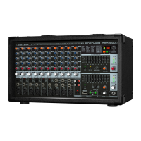
EUROPOWER PMP2000 Controls
(EN) Step 2: Controls
(1) The FX control determines the signal level that
is routed from the respective channel to the
built-in eects processor.
(2) The HIGH control in the EQ section governs
the high frequencies of the respectivechannel.
(3) Use the MID control to boost/cut the
midrange.
(4) The LOW control allows you to raise or lower
the bass frequencies.
(5) The MON control determines the channel’s
volume assigned to the monitor mix.
(6) Use the LEVEL control to set the volume level
of the respective channel.
(7) Use the CLIP LED to ensure that the input gain
is set properly. The CLIP LED should light up
only with peak signals, but never all the time.
(8) The PAD button reduces the channel
input sensitivity by 25 dB. Thus, you can
also connect high-level line signals to the
respective channel input.
(9) This HI-Z/LINE input can be used to connect
line level signal sources, such as keyboards,
electric and bass guitars.
(10) This is the channel’s balanced XLR
microphoneinput.
(11) The stereo line input of channels 7 - 12 can be
used to connect, for example, keyboards with
stereo outputs or a stereo drum computer.
(12) The CD/TAPE/LINE IN RCA input of channel
13/14 allows you to feed in external stereo
signals from your CD player or tape deck,
forexample.
(13) The CD/TAPE/LINE OUT RCA output
provides the stereo main mix signal of
your PMP2000 and can be routed to, say,
a recording machine.
(14) The phantom power supply provides the
voltage necessary for the operation of
condenser microphones. Use the PHANTOM
POWER switch to activate the supply together
for channels 1 - 12 (XLR connector). The LED
above the switch is lit when phantom power
is on.
(15) This is the PMP2000’s graphic stereo equalizer,
which comprises two units and can be used to
adapt the sound to the room acoustics.
(16) Use the EQ IN buttons to switch the two
equalizer units on or o.
(17) Press the RUMBLE FILTER button to activate
the low-cut lter of channels 1 - 6. This lter
eliminates unpleasant bass frequencies
(e.g.microphone pop noise).
(18) The FX TO MON control determines the eects
intensity of the multi-eects processor as
part of the monitor mix. Turn the control fully
counter-clockwise to add no eect to the
monitor mix.
(19) The MONITOR LEVEL control adjusts the
volume of the monitor mix.
(20) Use the MONITOR LEVEL display to control
the monitor signal level. The upper LED (LIM)
lights up when the built-in limiter is activated,
thus protecting against overload.
(21) With this MODE switch you can determine
whether the PMP2000 works as a stereo
amplier (“LEFT/RIGHT”) or as a dual mono
amplier (“MON/MAIN”). Please note that the
equalizer function also depends on this switch
setting (see (15)).
(22) The FX TO MAIN control functions as FX return
for the built-in eects processor. Use this
control to add the desired eect signal to the
main mix. No eect signal is added when the
FX TO MAIN is set fully counter-clockwise.
(23) The MAIN LEVEL control governs the overall
volume of the PMP2000.
(24) The MAIN LEVEL display reads the output
level of the PMP2000. The upper LED (LIM)
lights up when the built-in limiter is activated,
thus protecting against signal peaks.
(25) Use the FX FOOTSW(itch) jack to connect
any commercially available foot controller.
Itallows you to bypass the eects unit.
(26) This is the balanced MONITOR output of your
PMP2000. Use it to feed an external monitor
amp or active wedge.
(27) These two ¼" TS jacks allow you to route
the output signal to an external amplier.
Thisallows you to, say, use only the mixing
and eect section of the PMP2000. The signal
is taken pre-power amp. Of course, you can
also use only the left jack as a mono output.
(28) These two ¼" TS jacks can be used to
connect external signals, such as the main
mix signal from an additional mixing console
(pre-power amp).
(29) Here, you will nd a list of all multi-eect
presets available.
(30) This is the LED level meter of the eects
processor. Please make sure that the clip
LED lights up with signal peaks only. If it is
lit constantly, this indicates that the eects
processor is overdriven, which can lead to
unpleasant distortion.
(31) The Eect display reads the currently
selectedpreset.
(32) Turn the PROGRAM control to select the
eect presets. Press the control briey to
conrm your selection.
(33) The mains connection is on a standard IEC
receptacle. An appropriate power cord is
supplied with the unit.
(34) FUSE HOLDER. Before connecting the unit
to the mains, ensure that the voltage setting
matches your local voltage. Blown fuses
should only be replaced by fuses of the same
type and rating.
(35) Use the POWER switch to put your PMP2000
into operation. The POWER switch should
always be in the “O” position when you are
about to connect your unit to the mains.
(36) This is the RIGHT/MONO MAIN loudspeaker
output of your PMP2000, where you can
connect the right loudspeaker of a stereo
system. For this purpose, switch (21) must be
set to its upper position. If, however, you run
a mono main mix (switch (21) set to its lower
position), this loudspeaker output provides the
main mix signal in mono.
(37) The BRIDGE loudspeaker output allows
you to combine the left and right stereo
channel in one mono output, which is useful
for applications that require the use of one
loudspeaker only. To use the BRIDGE output,
switch (21) must be set to “LEFT/RIGHT”.
(38) This is the LEFT/MONITOR loudspeaker
output of your PMP2000, to which you can
connect the left loudspeaker of a stereo
system (switch (21) set to its upper position).
If you do a main mix in mono (switch (21) set
to its lower position), this loudspeaker output
provides the monitor signal in mono.
(39) SERIAL NUMBER.
Check Out behringer.com for Full Manual

 Loading...