34
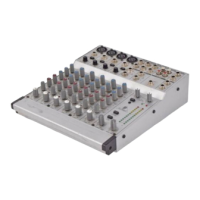
Fig. 4.9: Connecting several consoles via their Expander Ports
With the Expander Port inputs and outputs of your MX3242X you can route the following buses to the
outside world, and feed in the following external signals:
PIN-NR. DOCK INPUT DOCK OUTPUT
1 AUX SEND 1 AUX SEND 1
2 AUX SEND 2 AUX SEND 2
3 AUX SEND 3 AUX SEND 3
4 AUX SEND 4 AUX SEND 4
5 AUX SEND 5 AUX SEND 5
6 AUX SEND 6 AUX SEND 6
7 SUBGROUP 1 SUBGROUP 1
8 SUBGROUP 2 SUBGROUP 2
9 SUBGROUP 3 SUBGROUP 3
10 SUBGROUP 4 SUBGROUP 4
11 MIX-B L MIX-B L
12 MIX-B R MIX-B R
13 MAIN L MAIN L
14 MAIN R MAIN R
15
Tab. 4.1: Assignment of Expander Port inputs/outputs
4.4.2 Modifications
The modifications described below require some soldering skills, and should therefore be attempted only if
you have sufficient experience in soldering. If in doubt, please contact an electronics expert.
+ Please note that any one of the modifications listed below will void your warranty rights.
The pc boards (2 boards, each with 8 mono and 8 Mix-B input channels) can be accessed when you remove
the entire bottom panel of your MX3242X. One board each is used for channels 1 through 8, and 9 through
16. The two boards are identical and labeled the same.
The ends of the jumpers to be soldered in should not be inserted into the holes, but soldered flat to them! Bend
the jumper a little bit up between the two points of rest. A wire with plastic insulation stripped off at the ends will
work fine!
4. APPLICATIONS
 Loading...