7
ULTRAMIZER PRO DSP1424P
The mains connection of the ULTRAMIZERPRO is made by using the supplied cable. It meets all of the
international safety certification requirements. Please make sure that all units have a proper ground connec-
tion.
+ Before you connect your ULTRAMIZERPRO to the mains, please make sure that your local
voltage matches the voltage required by the unit (see chapter 6 SPECIFICATIONS for details)!
As a standard the audio inputs and outputs on the BEHRINGER ULTRAMIZERPRO are fully balanced. If
possible, connect the unit to other devices in a balanced configuration to allow for maximum interference
immunity. The automatic servo function detects unbalanced connections and compensates the level difference
automatically (6dB correction).
The MIDI links (IN/OUT/THRU) are made over standardized DIN patch cords. The data communication is
isolated from ground by an opto-coupler.
1.3 Control elements
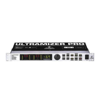
Fig. 1.1: ULTRAMIZERPRO front panel
The BEHRINGER ULTRAMIZERPRO is equipped with ten illuminated parameter keys, one jog wheel (rotary
control), a numeric display, 8 LED indicators and a power switch. Each of the two fully independent channels
can be monitored with four 8-stage LED meters, displaying input level, output level and gain reduction for both
bands.
1.3.1 Front panel
Fig. 1.2: Display section DSP1424P
The two LED chains read the input signal level indB, referenced to the internal digital maximum.
+ Please note that the nominal level of the ULTRAMIZERPRO can be selected with the
+4dBu/-10dBV switch located on the back panel (see chapter 3.1).
The gain reduction meters show the applied gain reduction. Gain reduction is shown for both frequency
bands. GRLO shows the gain reduction in the lower and GRHI in the higher frequency band.
After power-up, the LED display reads the number of the preset last used. This clearly legible, 2½ digit
numeric display has plus/minus indicators to show that parameters are being incremented or decremented
in edit mode.
1. INTRODUCTION
 Loading...