10
BEKOMAT 13, 13 CO, 13 CO PN25, 13 CO PN50
Electrical installation • Instalación eléctrica
Installation electrique • Elektrische Installation
english
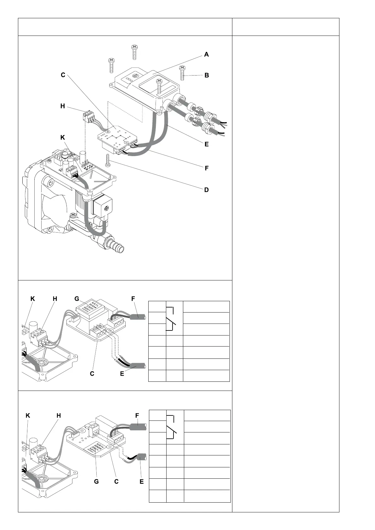
• Lift off domed cover (A) after removing
the 4 screws (B).
• Take power supply board (C) out of the
domed cover (A) after removing th e
screw (D).
• Guide cables for power supply (E)
and potential-free contact (F) through
screwed cable ttings.
• Terminals
Check type plate (G) for permissible
mains voltage and ensure confor-
mity!
VAC power supply 0.0 L
0.1 N
0.2 PE
24 VDC power supply +24 VDC (0V)
0V (+24 VDC)
In the case of 24 VDC operation, do
not connect +24 VDC to frame because
the internal housing potential of the
device is negative.
• Connect potential-free contact (F) to
terminals 0.6 - 0.7 (fail safe) or 0.7 - 0.8
(open during malfunction).
• Pull cable (E + F) tight and screw down
cable ttings.
• Screw power supply board (G) with
screw (D) into domed cover (A)
• Plug ribbon cable (H) into control
PCB (K)
• If the individual wires have not been
screwed into the plug, they should be
attached as follows: 1.0 = brown
1.1 = blue
2.0 = black
• Put on top of cover (A) and tighten the
4 screws (B)
Please note:
The power supply board (C) is in a
reverse position (upside down) in the
domed cover (A).
During no-load operation, a voltage of up
to 36 VDC may be measured at terminals
1.0 and 1.1(plug ribbon cable (H)).
Please ensure that the installation is
carried out according to the valid regula-
tions.
24 VDC - voltage
VAC - voltages
0.8
0.7
0.6
0.2
0.1
0.0
normally open
common
normally closed
Earth/Ground
Neutral
Phase
PE
N
L
0.8
0.7
0.6
normally open
common
normally closed
+24 VDC (0V)
0V (+24 VDC)
±24V
±24V
 Loading...