Do you have a question about the bel Digital Audio BMA2-4SHD and is the answer not in the manual?
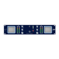
Key capabilities and hardware features of the BMA2-4SHD, including audio inputs, speakers, and alarm functions.
How to choose audio inputs from Analog, AES, or SDI sources for monitoring and bargraph display.
Details on setting up and managing audio loss, over-level, and anti-phase alarms.
Selection of bargraph ballistics (AES, DIN, VU, etc.) and scale types via internal switches.
Overview of rear panel connections including BNC, D-type, and headphone sockets.
Detailed pinout configuration for the 9-way sub-D female alarms connector.
Pinout details for the 9-way D female RS232 serial port for PC communication.
Procedure for setting analog input signal levels using internal switches and potentiometers.
How to configure the output levels for the left and right monitor outputs via internal switches.
Internal adjustment for the alarm tone level and its effect on rotation.
Configuration of bargraph display settings, including scale type, peak hold, and red/amber zones.
Instructions for applying physical scale graticules to the front panel bargraph displays.
Key features of the MonitorMx software for remote monitoring and control of BM-A series units.
Overview of the software's main screen, status indicators, and controls for monitoring.
Step-by-step guide to launching and connecting the software to the unit.
How to identify and manage multiple BM-A series units connected to the software.
Enabling and managing specific alarm categories (audio loss, over-level) within the software.
Managing system-wide alarms, including flashing and audible alerts from connected units.
Procedures for clearing active alarms from individual units or the entire system.
Disabling audible alarm notifications via the software interface.
Selecting input sources (Composite, SDI, AES, Analog) for monitoring through the software.
How meter type, peak hold, and reference settings are read and configured via internal switches.
Adjusting the red and amber color zones for the bargraph displays using software controls.
Option to disable the unit's front panel controls remotely via the MonitorMx software.
Instructions for installing the MonitorMx remote control and status software on a PC.
Requirements and pinout for the null-modem cable connecting the unit to a PC for software communication.
Introduction to the serial communication protocol for remote control of BM-A series units.
Structure of data frames including start/end flags, addresses, command, data, and checksum.
List of hexadecimal commands (e.g., 0x80-0x86) for remote control of unit functions.
Explanation of how the unit responds to commands with ACK (OK) or NAK (send again).
Details on data structures for commands like 'Set up switches' and 'Request Detail'.
Codes used to select video inputs (SDI 1, SDI 2, Remote) via serial commands.
Codes for selecting audio inputs (1-4) for the left and right speakers via serial.
Command to replace the current SDI image with color bars.
Data structure for defining the length and origin of the bargraph red zone via serial.
Data structure for defining the length and attachment of the bargraph amber zone via serial.
Codes used to select different bargraph display types (AES, DIN, VU, BBC, Extended VU, Nordic).
Bits used to select the timing for the bargraph peak indicator (hold times).
Bit for applying an offset (-18dB or -20dB) when AES input is used with an analog bargraph.
Data format for configuring alarm conditions (Auto, Anti-Phase, Over-level) via serial commands.
Command to request comprehensive unit status and alarm information via serial.
Command to retrieve the current front panel and internal switch configurations via serial.
Format of standard acknowledgement frames containing brief alarm and status information.
Format of negative acknowledgement frames indicating errors and checksum issues.
List of error codes (1-3) and their corresponding messages for NACK replies.
Specifies RS232 communication parameters: 8 data bits, no parity, 2 stop bits, 9600 Baud.
Explanation of the status and error indications provided by the front panel LEDs (ON, LIMIT, AES, SD, HD, NTSC, Phase).
Common issues like no power, incorrect bargraphs, persistent alarms, with their resolutions.
Technical details on analog input impedance (25kΩ) and digital input impedance (110Ω/75Ω).
Specifications for max output level (+15dB) and noise+THD (-95dB Analog, -98dB AES).
Frequency response range for all analog outputs: 20 Hz to 20kHz ±1dB.
Noise and THD specifications (-80dB) for the main drive amplifier.
Peak acoustic level (100dB SPL @2ft) and shielding (Magnetic) for the speaker units.
Description of the 4 hi-resolution tri-color bargraph level meters.
Supported video input standards: 1 x SD SMPTE 259M and 1 x HD SMPTE 296M, 274M.
Details on dynamic range, attack time, and fallback time for various bargraph scales (NORDIC, DIN, BBC, VU, AES).
List of alarm conditions monitored: audio loss, over-level, sustained anti-phase, AES/EBU carrier loss.
Rack mount size (2U high) and outline dimensions in mm and inches.
Power consumption (100W max), voltage range (90-264 VAC), frequency (50-60Hz), and fuse rating (4A).
Operating temperature (0°C to 30°C) and humidity (70% max) limits.
Unit weight specified in pounds (14lbs) and kilograms (6kg).
Type of computer interface: 9 pin RS-232 male PC-AT serial interface (null-modem).
| Brand | bel Digital Audio |
|---|---|
| Model | BMA2-4SHD |
| Category | Monitor |
| Language | English |