Do you have a question about the Belden Grass Valley DENSITE 3+ FR1 and is the answer not in the manual?
Explains the meaning of various safety and warning symbols used in the manual.
Details potential hazards to personnel, including injury or death, and provides general warnings for equipment operation.
Details potential hazards to equipment, indicating risks of damage, and provides cautions for operation.
Provides procedures and precautions to prevent damage to electronic components from electrostatic discharge.
Offers precautions for eye safety and handling of LCD/TFT displays to prevent damage or injury.
Information on product recycling procedures.
Confirmation of compliance with various safety standards like CSA, UL, IEC, EN.
Confirmation of compliance with various safety standards like CSA, UL, IEC, EN.
Information regarding compliance with laser product safety standards.
Provides a general introduction to the Densité 3+ FR1 Housing Frame.
Highlights the main capabilities and advantages of the Densité 3+ FR1 Housing Frame.
Details additional features and configurations available for the Densité 3+ FR1 Housing Frame.
Explains the compatibility and use of Densité 2 and 3 series cards with the frame.
Identifies the specific slot and cards designated for system functions within the frame.
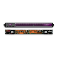
Provides a detailed description of the Densité 3+ FR1 Housing Frame.
Describes the physical arrangement and sections of the Densité 3+ FR1 Housing Frame.
Details the inputs, outputs, and components located on the rear panel of the frame.
Guides the user through the physical installation process of the Densité 3+ FR1 Housing Frame.
Lists the items that should be included with the Densité 3+ FR1 frame upon delivery.
Provides instructions on how to open the front door of the Densité 3+ FR1 frame.
Explains how to physically install the Densité 3+ FR1 housing frame into a standard 19" rack.
Guides the user through the process of installing cards into the Densité 3+ FR1 frame.
Details the use of adapters required to install older Densité 2 cards into the Densité 3+ FR1 frame.
Instructions for installing clips to secure power cords and prevent accidental disconnection.
Explains the frame's cooling system, including fans, air filters, and ventilation slots.
Describes how to adjust the speed of the frame's cooling fans using a slider switch.
Explains the function of the GPI connector for alarm reporting.
Identifies components within the frame that can be serviced or replaced by field personnel.
Provides instructions for installing or replacing the power supply units in the Densité 3+ FR1 frame.
Detailed steps for removing and installing the controller card in the Densité 3+ FR1 frame.
Instructions on how to replace a failed fan assembly in the frame.
Guides on how to install and replace the optional system card in the Densité 3+ FR1 frame.
Lists the technical specifications of the Densité 3+ FR1 Housing Frame, including mechanical, power, cooling, and communication details.
Introduces the CPU-ETH2 Controller card and its role in the Densité 3+ FR1 frame.
Highlights the key features and capabilities of the CPU-ETH2 Controller card.
Describes the methods for controlling and configuring the CPU-ETH2 controller card.
Explains how to use the Ethernet interface for remote control and configuration via iControl.
Details how to use the on-board control panel for local configuration and operation of the CPU-ETH2 controller.
Explains the meaning of the multi-color status LED on the controller card for indicating operational status and alarms.
Guides the user through the configuration processes for the CPU-ETH2 controller.
Provides step-by-step instructions for configuring network settings like IP address, subnet mask, and gateway.
Explains how to identify the CPU-ETH2 controller within the iControl system using labels and source IDs.
Describes how the CPU-ETH2 controller monitors the frame's status, including power supplies, fans, and network ports.
Reports the status of the frame's CPU, fans, and power supplies via the iControl interface.
Provides status information for the two Ethernet ports on the CPU-ETH2 card via iControl.
Displays current send/receive data rates and speed for all installed cards in the Densité frame.
Reports on the CPU, memory, and flash usage of the CPU-ETH2 controller card.
Explains how the CPU-ETH2 card can function as an SNMP agent to send traps to designated targets.
Describes how to back up and restore configuration data for Densité-series cards using the CPU-ETH2 controller.
Instructions for restoring CPU-ETH2 controller settings to their default factory values.
Explains how to manage the time and date settings of the CPU-ETH2 controller, including NTP synchronization.
Details how the CPU-ETH2 controller generates and reports alarms for the frame and its components.
Guides the user on configuring alarm reporting levels and contributions for the CPU-ETH2 controller.
Describes available options for the CPU-ETH2 controller, such as Ethernet Link Redundancy.
Presents the complete on-board menu structure for the CPU-ETH2 controller accessed via its local panel.
Introduces the REF-1801-FR1 reference module and its function in the Densité 3+ FR1 frame.
Highlights the key features of the REF-1801-FR1, including digital reference generation and timecode extraction.
Illustrates the functional block diagram of the REF-1801-FR1 Frame Reference card.
Shows the layout of controls and indicators on the front edge of the REF-1801-FR1 card.
Describes various use cases and applications for the REF-1801-FR1 module.
Describes the application of the REF-1801-FR1 for distributing URS4D signals and managing frame sync.
Explains how to use the REF-1801-FR1 to synchronize multiple Densité frames using reference signals and timecode.
Provides guidance on the installation process for the REF-1801-FR1 Frame Reference card.
Lists the items included in the REF-1801-FR1 package.
Details the correct procedure for mounting the REF-1801-FR1 module and its rear panel into the frame.
Describes the rear panel connections for the REF-1801-FR1, including reference and timecode inputs.
Covers the operational aspects and control methods for the REF-1801-FR1.
Outlines the two primary control interfaces for the REF-1801-FR1: local panel and iControl.
Explains how to control the REF-1801-FR1 using the frame's controller card and its local panel.
Details the status monitor LED on the REF-1801 card, its colors, and fault reporting.
Provides an overview of the iControl interface window for the REF-1801-FR1, detailing its sections and status icons.
Describes the controls and status monitors within the Input tab of the REF-1801-FR1 iControl interface.
Explains the settings for the URS generator operating mode (Normal and Free Run) on the REF-1801-FR1.
Details the Alarms tab in iControl, including timecode logging and alarm configuration for the REF-1801-FR1.
Describes the Info tab in iControl for entering and viewing card identification details and manufacturing information.
Lists the technical specifications for the REF-1801-FR1, including Genlock input, signal types, and power.
| Category | Controller |
|---|---|
| Model | DENSITE 3+ FR1 |
| Manufacturer | Belden Grass Valley |
| Type | Modular Frame |
| Power Supply | Redundant, Hot-swappable |
| Input Voltage | 100-240 VAC, 50/60 Hz |
| Certifications | CE, UL, FCC |
| Input Ports | Varies with installed modules |
| Output Ports | Varies with installed modules |
| Supported Formats | Various (depending on installed modules) |
| Control Interface | Ethernet |
| Operating Temperature | 0°C to 40°C (32°F to 104°F) |
| Storage Temperature | -20 to 70 °C |
| Compatibility | DENSITE series modules |