6
– Pin configuration of the RJ45 socket,
RS2-xTX/xFX EEC:
– 1 line pair: pin 3 and pin 6
– 1 line pair: pin 1 and pin 2
– remaining pins: not used.
Fig. 3: Pin configuration of a TP/TX
interface
100 Mbit/s connection (FX port)
The 100 MBit/s ports of the
RS2-xTX/xFX EEC,
- one port on the RS2-4TX/1FX…
- two ports on the RS2-3TX/2FX… support
the IEEE 802.3 100BASE-FX FDX standard.
They use a duplex SC connector or a ST
connector (on RS2-4TX/1FX-ST EEC). Each
100 MBit/s port allows one further DTE or
an optical network component to be
connected.
5pin terminal block
The supply voltage and the indicator
contact are connected via a 5pin terminal
block. If the terminal block is fitted the
wrong way round, the device will still work
correctly.
z
Warning!
The RS2-xTX/xFX EEC equipments
are designed for operation with a
safety extra-low voltage. Thus, they
may only be connected to the sup-
ply voltage connections with SELV
circuits with the voltage restrictions
in accordance with IEC/EN 60950-1.
Pin 8
Pin 7
Pin 6
Pin 5
Pin 4
Pin 3
Pin 2
Pin 1
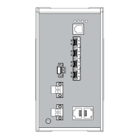
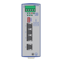
Fig. 2: Display elements of the
RS2-xTX/xFX EEC
1.6 INTERFACES
10/100 MBit/s connection (TP port)
The 10/100 Mbit ports of the RS2-xTX/xFX
EEC (8-pin shielded R45 sockets),
- three ports on the RS2-3TX/2FX…
- four ports on the RS2-4TX/1FX…
allow DTEs or independent network seg-
ments complying with the standards IEEE
802.3 100BASE-TX / 10BASE-T to be
connected. These ports support autonego-
tiation, the autopolarity function and
autocrossing.
The socket casings are electrically connec-
ted to the front panel of the RS2-xTX/xFX
EEC.
LEDs for power
(P1 and P2)
LEDs for data, link status
(DA/STAT 1 to 5)
FAULT
LED
LEDs for power
(P1 and P2)
LEDs for data, link status
(DA/STAT 1 to 5)
on the RS2-4TX EEC
FAULT
LED
234
DA/STAT
12
P
1
DA/STAT
FAULT
234
DA/STAT
12
5
P
1
DA/STAT
FAULT
– Voltage supply: Redundant voltage sup-
plies are supported. Both inputs are
decoupled. There is no load distribution.
With redundant supply, the power pack
supplies the RS2-xTX/xFX EEC only with
the higher output voltage. The supply vol-
tage is electrically isolated from the hou-
sing.
Fig. 5: Pin configuration of 5 pin terminal
block
– Indicator contact:
The indicator contact is used to supervise
the functions of the RS2-xTX/xFX EEC and
thus facilitates remote diagnosis without
management software.
Contact interrupt indicates the following
by means of a potential-free indicator
contact (relay contact, closed circuit):
– the failure of at least one of the two
supply voltages (supply voltage 1 or 2
< 9.6 V).
– a permanent fault in the RS2-xTX/xFX
EEC (internal voltage supply).
– the faulty link status of at least one port.
The indication of the link state on the
RS2-xTX/xFX EEC can be masked on a
port-by-port basis using the DIP swit-
ches LA1 to LA5 (LA1 to LA4 on
RS2-4TX EEC).
State of delivery: link test is activated.
Ground connection
The RS2-xTX/xFX EEC is grounded via a
separate screw connection.
+24V
+24V*
FAULT
= 0V
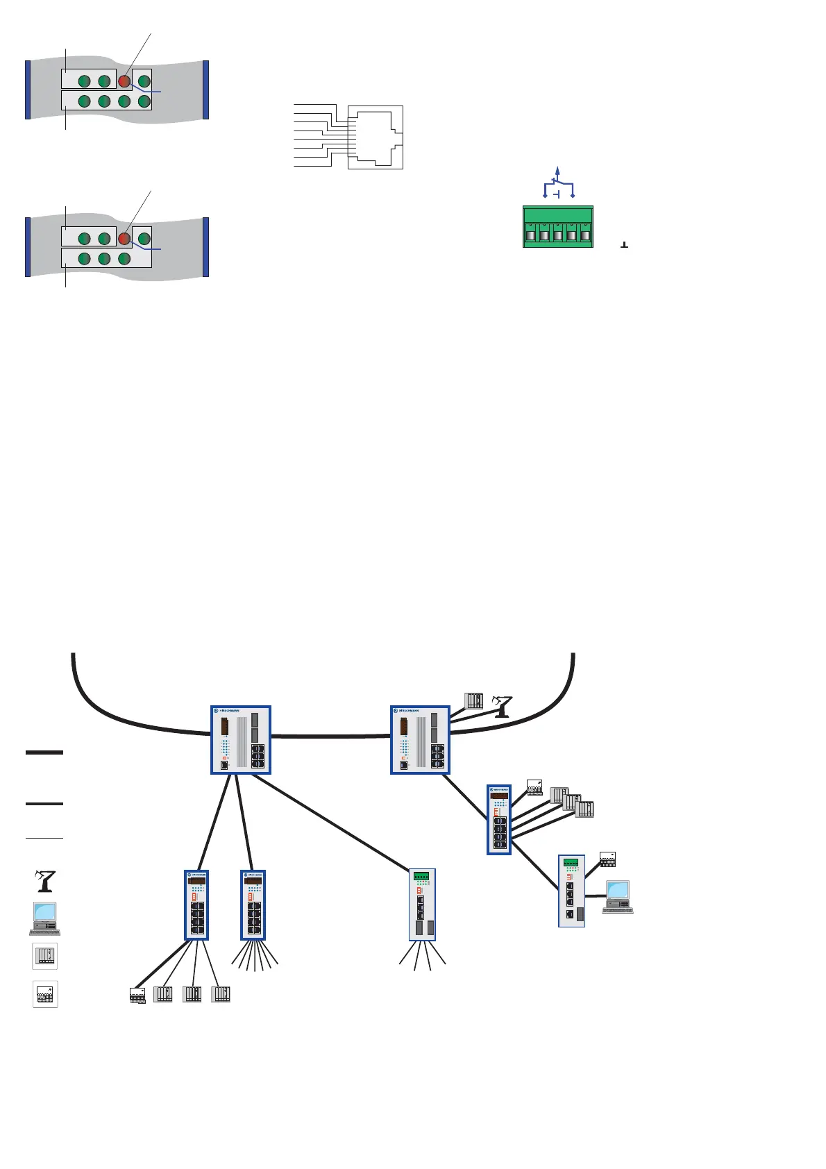
Fig. 4: Configuration with RS2-xTX/xFX EEC: Connection of up to 4 data terminal equipments (4 on RS2-4TX/1FX…, 3 on RS2-3TX/2FX…)
or further segments via TP/TX as well as connection via fiber optic cable with up to 2 optical ports (1 on RS2-4TX/1FX…, 2 on RS2-
3TX/2FX….
robot
user
station
PLC
I/O block
100 Mbit/s
HIPER-Ring
100 Mbit/s
10 Mbit/s
RS2-FX/FX
RS2-FX/FX
RS2-TX
RS2-4TX/1FX
RS2-3TX/2FX
RS2-3TX/2FX
x
RS2-4TX/1FX
x
 Loading...