6
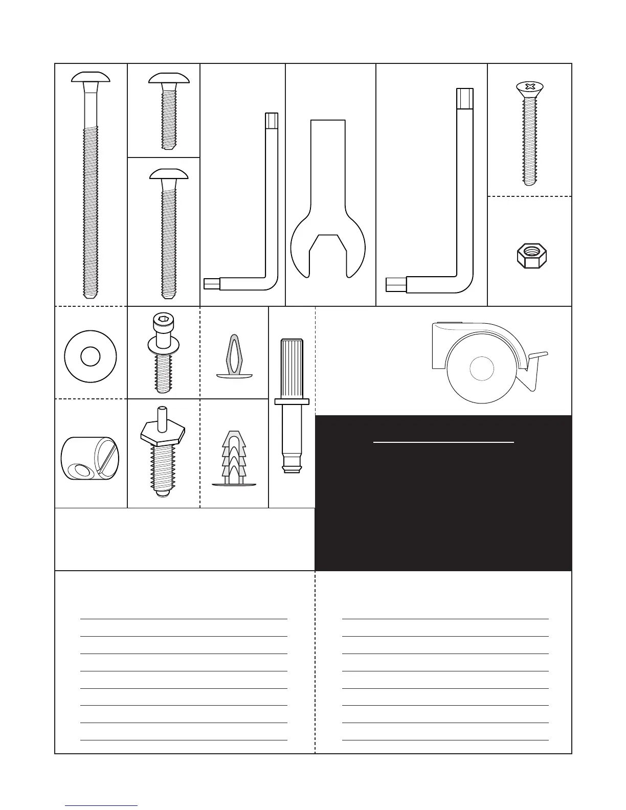
HARDWARE DIAGRAM (SCALE 1:1)
E
A
DQ
C
BY
2
FH
N
G
X
Y
X1
Y1
A – Screw 4
B – Small wrench 1
C – Nuts 8
D – Plastic round washers 8
E – Screw 8
F – Large wrench 1
G – Nuts 8
H – Screw 8
N – Screw 4
X – Screw 4
Y – Screw with pin 4
Y2 – Spanner 1
Q – Caster stud 4
R – Caster
(n° 2 with brake)
4
X1– Hole masking cap 8
Y1 – Hole masking cap 4
TOOLS REQUIRED FOR ASSEMBLY:
METRIC ALLEN WRENCH (INCLUDED)
STANDARD SIZE SCREWDRIVER (NOT INCLUDED)
HAMMER (NOT INCLUDED)
HARDWARE QUANTITY HARDWARE QUANTITY
R
(SCALE 1:2)
IMPORT ANT:
Before commencing assembly, check that
screws E and nuts C screw together
correctly and that pins X and Y can be
inserted into the holes pre-drilled
in the legs (see diagram 6).
If not, please contact your dealer.