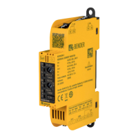
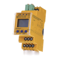
LINETRAXX® RCM420
2.3.1 Connection monitoring
The CT connections are continuously monitored. In the event of a fault, the alarm relays K1 / K2 switch without
delay, the alarm LEDs AL1 / AL2 / ON flash (Error Code E.01). After eliminating the fault, the alarm relays
automatically return to their initial position, provided that the fault memory M is deactivated. With the fault
memory activated, K1/K2 return to their initial position by pressing the reset button R. A second cascaded
measuring current transformer will not be monitored.
2.3.2 Fast response value query
With the display in standard mode, the currently measured response values I
Δn1
and I
Δn2
can be queried
pressing the Up and Down keys ( < 1.5 s). Switchover to the Menu mode is not required. If you want to exit the
fast response value query, press the enter key.
2.3.3 Automatic self test
The device automatically carries out a self test after connecting to the system to be monitored and later every
24 hours. During the self test internal functional faults will be detected and appear in form of an error code on
the display.
The alarm relays are not checked during this test.
2.3.4 Manual self test
After pressing the test button for > 1.5 s, the device carries out a self test. During this test, internal functional
faults are detected and will be displayed in form of an error code. The alarm relays are not checked during this
test.
While the test button T is pressed and held down, all device-related display elements appear on the display.
2.3.5 Functional faults
If an internal functional fault occurs, all three LEDs flash. An error code will appear on the display (E01…E32). In
such a case please contact the Bender Service.
2.3.6 Set the number of reload cycles
If faults occur only temporarily, but recurrently, in the system being monitored, with the fault memory M
deactivated, the alarm relays would switch synchronously to the error status. RL in the out menu can be
used to limit the number of these changeover processes. As soon as the preset number of switching cycles is
exceeded, the fault memory will come on and an activated alarm remains stored.
2.3.7 Assigning alarm categories to alarm relays K1/K2
The alarm categories device error, residual current I
Δn1
, residual current I
Δn2
or alarm by device test can be
assigned to the alarm relays via the ‘out’ menu.
2.3.8 Time delays t, t
on
and t
off
The times t, t
on
and t
off
described below, delay the output of alarms via LEDs and relays.
Starting delay t
After connection to the supply voltage, the alarm indication is delayed by the preset time t (0…10 s).
Response delay t
on1/2
RCM420_D00057_06_M_XXEN/12.2023 9

 Loading...


