13
CP.BULL8 OM CONTROL UNIT
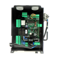
WIRE DIAGRAM
Wire connections shown in Fig. 1 are described hereunder:
Terminals Function Description
L/N Power supply
CP.BULL8 OM: Input, 230Vac 50Hz (L-Phase/N-Neutral)
CP.BULL8 OM 115: Input, 115Vac 60Hz (L-Phase/N-Neutral)
GND GND Earth (compulsory)
ANT/SHIELD Antenna
Connection antenna to the built-in receiver
(ANT-signal/SHIELD-screen).
+12V COMMON Common for control inputs.
PP Step-by-Step
Input, step-by-step push-button (N.O. contact)
Presettable as Input, OPEN with OPCL logics.
PED PEDESTRIAN
Input, pedestrian push-button (N.O. contact). It controls the partial opening, configurable
through parameter TPED. At end of TCA time (if activated), closure control signal is sent.
Presettable as Input, CLOSE with OPCL logics.
STOP STOP Input, STOP push-button (N.C. contact)
PHO PHOT O
Input, (N.C. contact) for safety devices (e.g. photocells).
During closure: if the contact is opened, the motor stops. With OPCL logics, when the
photocell is no longer obscured, the motor reversion occurs (gate opens).
During opening: if the contact is opened, the motor stops. with OPCL logics When the
photocell is no longer obscured, the motor restarts opening.
PHA PHOT C
Input, (N.C. contact) for safety devices (e.g. photocells).
During closure: it can be preset by PHCL logics.
During opening: it can be preset by PHCL logics.
+12V COMMON Common for control inputs.
BAR/BAR SENSITIVE EDGE
Input, sensitive edge contact
Resistive edge: Jumper “DAS” closed
Mechanical edge: Jumper “DAS” open
If the edge is activated, the gate stops and a movement reversion occurs for about 3 sec.
If the edge is not in use: Jumper “DAS” open, jumper between terminals BAR/BAR.
SCA
Service light
RX 2° Ch
PHOTO TEST
Free, N.O. contact. Presettable as:
- SCA (open gate indicator lamp): open contact when gate is closed, fast flashing light
when gate is closing, slow flashing light when gate is opening and closed contact
when gate is open. See wire diagram, Fig.2).
(Logics 2CH:OFF, SERL:OFF, TST1:OFF, TST2:OFF);
- Timed service light (see SERL logics and diagram in Fig.2);
- Output, second radio channel (see 2CH logics and diagram in Fig.2);
- PHOTO TEST to power the transmitters of photocells in TEST mode (see TST1, TST2
logics and diagram in Fig.3).
24Vac 24Vac Output, power supply of accessories, 24Vac/500mA max
ENC1 ENCODER Connector for connection of anti-crash sensor (ENCODER)
SWC SWC Input, CLOSE limit switch (N.C. contact)
SWO SWO Input, OPEN limit switch (N.C. contact)
TECHNICAL DATA
Contol unit supply
24 Vdc
Power supply
230 Vac 50/60 Hz or 115Vac 50/60Hz according to the version
Output supply
1 motor 230Vac
Power maximum motor
280 W
Output supply accessories
24Vac 500mA max.
Protection level
IP54
Operating temp.
-20°C / +50°C
Radio receiver
built in 433,92 MHz confgurabile (rolling-code or programmable + rolling-code)
Rolling code transmitters supported
64 rolling-code

 Loading...