6
ASSEMBLY
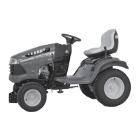
Slide the nylon bushing (item 1) the flange first, down
the lift arm (item 2) to the fork (item 3).
Slide the right support (item 4) down the lift arm and to
the nylon bushing.
Install the handgrip (item 5) on the lift arm.
Unscrew the two bolts (item 1) from the right hand side
of the tractor frame.
Install the assembled support (item 2) to the front of the
tractor frame by making sure to insert the end of the lift
arm into the sleeve on the left support and secure with
two carriage bolts (item 3) (the heads inside) and two
flange nuts on the outside.
Secure the rear with the original bolts (item 1).
Do not tighten the bolts now.
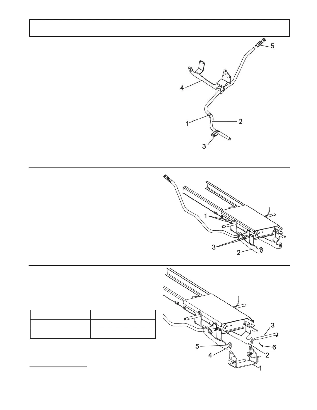
Install the pivot support (item 1) inside the front supports
(item 2). Insert the pin (item 3) into the appropriate holes
(items 4 or 5) of the front supports according to the chart
below.
Lock into place by placing the bended part of the pin in
the hole that is free.
Secure in place with one 3 mm hair pin (item 6).
Tighten all the bolts firmly.
Install the pivot support
Install the bushing and the lift arm
Install the right assembled support
Front Tire (size) Holes in front supports
15 x 6-6 Top holes (item 5)
16 x 6.5-8 Bottom holes (item 4)