CIAO e
5
Use the power cable supplied to connect the boiler to the
mains power supply.
If the power cable is replaced, use a cable type HAR H05V2V2-
F, 3 x 0.75 mm2, with max. outside diameter 7 mm.
3.4 Gas connection
Before connecting the appliance to the gas network, check that:
- national and local regulations are complied
- thegastypeistheonesuitablefortheappliance
- the piping is clean.
The gas pipe must be installed outdoor. If the pipe goes through the
wall, it must go through the central opening, in the lower part of the
template.Itisadvisabletoinstallalterofsuitabledimensionson
the gas line if the distribution network had solid particles.
Once the appliance has been installed check that connections are
sealed according to current installation regulations.
3.5 Fumes exhaustion and air suction (CIAO C.S.I. e)
For fumes exhaustion, refer to the current local and national regu-
lations.AlwayscomplywithlocalstandardsoftheFireDepartment,
theGasCompanyandwithpossiblemunicipaldispositions.
Thereleaseofcombustionproductsisassuredbyacentrifugalfan
placed inside the combustion chamber and its correct operation
isconstantlycheckedbyapressureswitch.Theboilerissupplied
withouttheuegasoutlet/airsuctionkit,sinceitispossibletouse
the accessories for appliance with a forced draught sealed cham-
ber that better adapts to the installation characteristics.
It is essential for ue gas release and the restoration of boiler
combustion air to usecertiedpipes and that connection is car-
riedoutcorrectlyasindicatedbytheinstructionssuppliedwiththe
uegasaccessories.Withonlyonesmokepipeyoucanconnect
morepiecesofapplianceprovidedthateverypieceofapplianceis
sealedchambertype.
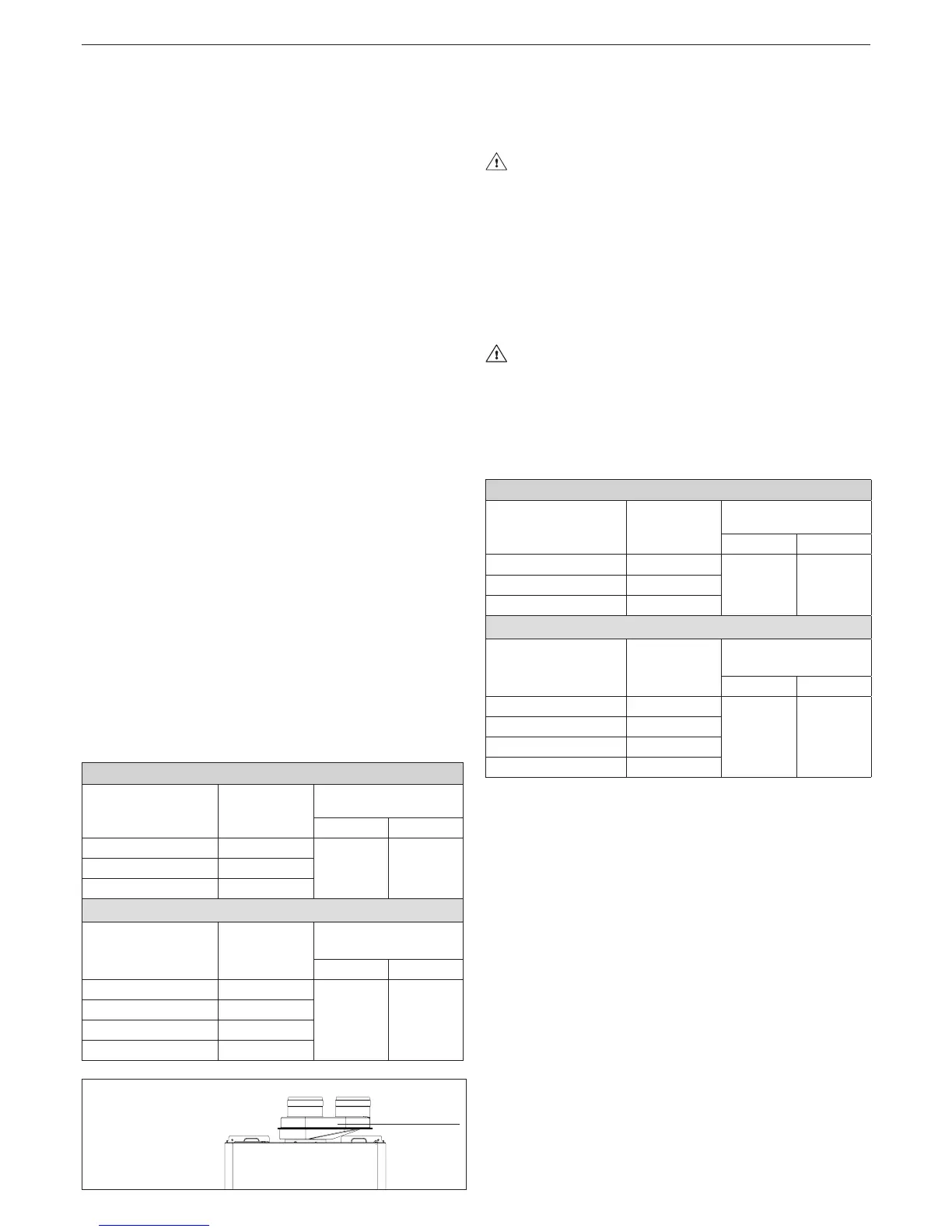
CONCENTRIC OUTLETS (ø 60-100)
The boiler has been designed to be connected to concentric outlet/
suctionpipesandwiththeopeningforairsuction(E)closed(g.
10).Theconcentricoutletscanbeplacesinthemostsuitabledi-
rectionaccordingtoroomrequirements,complyingwiththemaxi-
mum lengths indicated in the table. For installation, follow the in-
structions supplied with the kit. According to the length of the pipes
used,itisnecessarytoinsertaange,selectingonefromthose
containedintheboiler(seethefollowingtable).Whennecessary,
theuegasange(F)mustberemovedusingascrewdriverasa
lever. The table indicates the permitted linear lengths. According to
thelengthofthepipesused,itisnecessarytoinsertaange,select-
ingonefromthosecontainedintheboiler(seethefollowingtable).
24 C.S.I.
Pipe length
ø 60-100 [m]
Flue gas
ange (F)
Load losses for each
bend (m)
45° 90°
upto0,85
Ø 42
1 1,5
from0,85to2,35 Ø44(**)
from 2,35 to 4,25 not installed
28 C.S.I.
Pipe length
ø 60-100 [m]
Flue gas
ange (F)
Load losses for each
bend (m)
45° 90°
upto0,85 Ø 43
1 1,5
from0,85to1,7 Ø45(**)
from 1,7 to 2,7 Ø 47
from 2,7 to 3,4 not installed
(**)ttedinboiler
air/uegas
splitter
To direct the outlets in the most suit-
ableinstallationway(rightairinput)
there is an air/flue gas splitter kit
available.
TWIN OUTLETS (ø 80) (g. 11) (CIAO 24 C.S.I. e)
Twin outlets can be placed in the most suitable direction according
to the room requirements.
Tousethecombustionairsuctionpipe,oneofthetwoinlets(Gand
H)mustbeselected.Removetheclosureplugwhichisxedusing
screws,andusethespecicadaptorrelatingtotheinletselected.
Theairinletadaptorø80(X)mustbecorrectlyoriented,itis
thereforenecessarytoxitusingtheappropriatescrews,so
thatthelocatingtabdoesnotinterferewiththecasing:Xair
inletadaptorø80-Yairinletadaptorfromø60toø80.
Whennecessary,theuegasange(F)mustberemovedusing
a screwdriver as a lever. The table indicates the permitted linear
lengths.Accordingtothelengthofthepipesused,itisnecessary
toinsertaange,selectingonefromthosecontainedintheboiler
(seethefollowingtable).
TWIN OUTLETS (ø 80) (g. 11) (CIAO 28 C.S.I. e)
Twin outlets can be placed in the most suitable direction according
to the room requirements.
Theairinletadaptormustbecorrectlyoriented,itistherefore
necessarytoxitusingtheappropriatescrews,sothatthe
locating tab does not interfere with the casing.
Whennecessary,theuegasange(F)mustberemovedusing
a screwdriver as a lever. The table indicates the permitted linear
lengths.Accordingtothelengthofthepipesused,itisnecessary
toinsertaange,selectingonefromthosecontainedintheboiler
(seethefollowingtable).
24 C.S.I.
Pipe length
ø 80 [m]
Flue gas
ange (F)
Load losses for each
bend (m)
45° 90°
up to 2+2
Ø 42
1,2 1,7
from 2+2 to 6+6 Ø44(**)
from 6+6 to 16+16 not installed
28 C.S.I.
Pipe length
ø 80 [m]
Flue gas
ange (F)
Load losses for each
bend (m)
45° 90°
up to 3+3 Ø 43
1,2 1,7
from 3+3 to 7+7 Ø45(**)
from 7+7 to 11+11 Ø 47
from 11+11 to 14+14 not installed
(**)ttedinboiler

 Loading...