11
ENGLISH
At this point, the boiler starts automatically if correct operating conditions
have been restored; when the burner ignites, the green indicator led lights up
and the digital display indicates the instantaneous operating temperature.
Simply turning the selector to does not reset the boiler.
If the boiler continues not to work, call in the local Technical Assistance
Service.
In normal operating conditions, when the function selector is turned to
,
the digital display indicates “- -” (Fig. 12.11) unless the anti-freeze phase
(AF) is in progress or the combustion analysis function is activated (CO).
12.2 - Switching off
For short absences (weekends, brief journeys, etc.) turn the function
selector to
OFF/RESET.
The digital display will look like Fig. 12.11.
As the boiler remains powered with the gas tap open, it is protected by the
following systems:
• anti-freeze:
Heating
the function starts if the temperature measured by the delivery probe
falls below 6°C. In this phase, a heat demand is generated and the burner
ignites at minimum power. This is maintained until the temperature of the
delivery water reaches 35°C.
Domestic hot water (for R.S.I. only with connection to an external
water tank with probe)
the function starts if the temperature measured by the domestic hot
water probe (water tank probe for R.S.I. models) falls below 4°C. In this
phase, a heat demand is generated and the burner ignites at minimum
power. This is maintained until the temperature of the delivery water
reaches 55°C for C.S.I. - 35°C for R.S.I..
During the anti-freeze phase, AF flashes on the display (Fig. 12.12).
• circulator anti-block: if the boiler remains inactive, the circulator
performs a 30-second operating cycle every 24 hours.
If the boiler is planned not to be used for a long period, proceed as follows:
• move the function selector to OFF-RESET
• turn the main system switch to “off”
• close the fuel and the heating and hot water taps (for C.S.I.).
In this case, the anti-freeze and anti-block systems are disabled. Drain the
heating and hot water system (for C.S.I.) if there is danger of freezing.
12.3 - Indicator LEDs and faults
Green indicator LED
Off = boiler on stand-by, no flame
On = burner on, the boiler works regularly.
Red indicator LED
Stop: just the fault code flashes on the digital display.
Block: the red indicator LED lights up and the fault code flashes on the
digital display.
The fault code is not displayed in the OFF/RESET ( ) mode. To display it,
move the function selector to or . During combustion analysis and
the anti-freeze phase, instead, it is displayed.
To reset the boiler, turn the function selector to
(OFF/RESET) and then
move it to be required position: summer, winter or winter with preheating
(for C.S.I.) (Fig. 12.3).
If the boiler still doesn’t work, call in the local Technical Service Centre.
Code
AL10
AL20
AL21
AL29
AL60
AL60
AL71
AL73
AL28
AL26
AL79
AL41
AL40
AL34
AL52
AL55
AL91
Description of alarm
Ignition attempts finished (no flame/condensate present)
Limit thermostat fault
Low temperature thermostat/condensate pump safety
device fault
Fumes probe overtemperature
Domestic hot water probe fault (C.S.I.)
Water tank probe fault (R.S.I.)
Delivery probe fault (open/short circuit)
Return probe fault (open/short circuit)
Return/delivery probe differential fault
Return over temperature
Delivery over temperature / return-delivery probe
differential fault
System water pressure low
System water pressure low (after 10 minutes)
Fan tacho fault
Generic electronic fault
No boiler mode configuration fault (corresponding
jumper absent)
Clean primary exchanger (call the technical
assistance service)
Status
Block
Block
Block
Block
See dedicated
section
Block
Stop
Stop
Block
Block
Block
Stop
Block
Block
Block
Block
Signal
For C.S.I.
models only
12.2 12.3
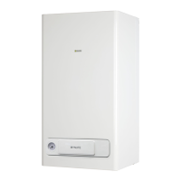
DHW mode CH mode
12.4 12.5
A green indicator LED
boiler status
12.6 12.7 12.8
B red
indicator
LED fault
12.9 12.10
12.11 12.12
12.13
Closed
position
Open
position
1 - Green indicator LED - flame present
2 - Digital display
3 - Red fault LED
4 - Housing for programmable timer (optional)
5 - Heating water temperature selector
6 - Function selector
7 - Domestic hot water temperature selector *
8 - Water gauge
* The parts of manual referring to the domestic hot water circuit should only be
considered if a water tank is installed, case C (accessory available on request)
1 23
876 5 4
12.1
12.16
A
MAX
MIN
B
12.17

 Loading...