13
ENGLISH
28 C.S.I.
32 C.S.I.
36 C.S.I.
12 R.S.I.
15 R.S.I.
25 R.S.I.
35 R.S.I.
rpm
rpm
rpm
rpm
rpm
rpm
rpm
Natural gas
(G20)
44
45
52
51
42
55
60
LPG
propane (G31)
43
45
52
51
41
54
60
Maximum heating fan rpm
Gas valve calibration
• Power the boiler.
• Open the gas tap.
• Turn the function selector to OFF/RESET (digit “--”).
• Pull off the domestic hot water temperature selector knob (7, Fig. 12.1)
and the domestic hot water function selector knob (6, Fig. 12.1).
• Press the combustion analysis button CO.
• Wait for the burner to ignite. “CO” is displayed on the digital display and
the boiler works at maximum heating power. The flue cleaner function
remains active for a maximum of 15 min; if a delivery temperature of 95°C
is reached, the burner switches off. It is re-ignited when this temperature
falls below 75°C.
• Remove the plug and insert the fumes analysis probe.
• Turn the max. heating trimmer clockwise until it reaches the maximum fan
rpm (see table).
28 C.S.I.
32 C.S.I.
36 C.S.I.
12 R.S.I.
15 R.S.I.
25 R.S.I.
35 R.S.I.
%
%
%
%
%
%
%
Natural gas
(G20)
9,0
9,0
9,0
9,0
9,0
9,0
9,0
LPG
propane (G31)
10,0
10,0
10,0
10,0
10,0
10,0
10,0
CO2 max
• Check the CO
2 value: if the value does not match that indicated in the
table, turn the maximum gas valve adjustment screw.
• Turn the max. heating trimmer anti-clockwise until it reaches the minimum
fan rpm (see table).
28 C.S.I.
32 C.S.I.
36 C.S.I.
12 R.S.I.
15 R.S.I.
25 R.S.I.
35 R.S.I.
%
%
%
%
%
%
%
Natural gas
(G20)
9,0
9,0
9,0
9,0
9,0
9,0
9,0
LPG
propane (G31)
10,0
10,0
10,0
10,0
10,0
10,0
10,0
CO2 min
• Check the CO
2 value: if the value does not match that indicated in the
table, turn the minimum gas valve adjustment screw.
• Turn the max. heating trimmer to the maximum heating fan rpm (see table)
• To exit the flue cleaner function, turn the control knob 6
• Remove the fumes analysis probe and put back the plug.
Remount the knobs on the panel. The “combustion analysis” function
automatically deactivates if the board generates an alarm.
If a fault develops during the combustion analysis phase, perform the release
procedure as follows:
Turn the function selector 6 to
, then to , and then move it to the
required function.
15 - GAS CONVERSION
It is easy to convert from one gas family to another even after the boiler has
been installed.
This operation must be performed by professionally qualified staff.
The boiler is designed to work with natural gas (G20), as indicated on the
product plate.
The boiler can be converted to propane using the relative kit supplied as an
accessory.
To disassemble, proceed as follows (Fig. 15.1):
• disconnect the boiler from the power supply and close the gas tap
• remove the shell and cover of the air distribution box
• release the panel and turn it forwards
• remove the gas pipe (D)
• remove the nozzle (E) contained in the gas train and replace it with the
one contained in the kit
• remount the gas train (check that the gas pipe connected to the fan mixer
is in position)
• put back the air distribution box cover
• power the boiler and open the gas tap.
Adjust the boiler as described in the “Adjustments” section, referring to LPG
data.
The boiler may only be converted by qualified staff.
After conversion, apply the new identification plate contained in the kit.
16 - CHECKING COMBUSTION PARAMETERS
To analyse combustion, proceed as follows:
• turn the function selector to OFF/RESET (digit “--”)
• pull out the central knob (6, Fig. 12.1) on the panel
• press the combustion analysis button (CO, Fig. 13.2)
• insert the analyser probes in the relative positions on the air distribution
box, after removing the screw F and the plug G (Fig. 15.2)
• check that the values of CO
2 correspond to those indicated in the table.
If the value displayed is different, modify it as indicated in the “Gas valve
calibration” section
• check combustion.
Then:
• remove the analyser probes and close the combustion analysis taps with
the relative screw cap
• put back the central knob 6 on the panel.
The fumes analysis probe must be fully inserted.
IMPORTANT
The function that switches off the boiler when water temperature reaches
a maximum of about 95°C is still enabled during the combustion analysis
phase.
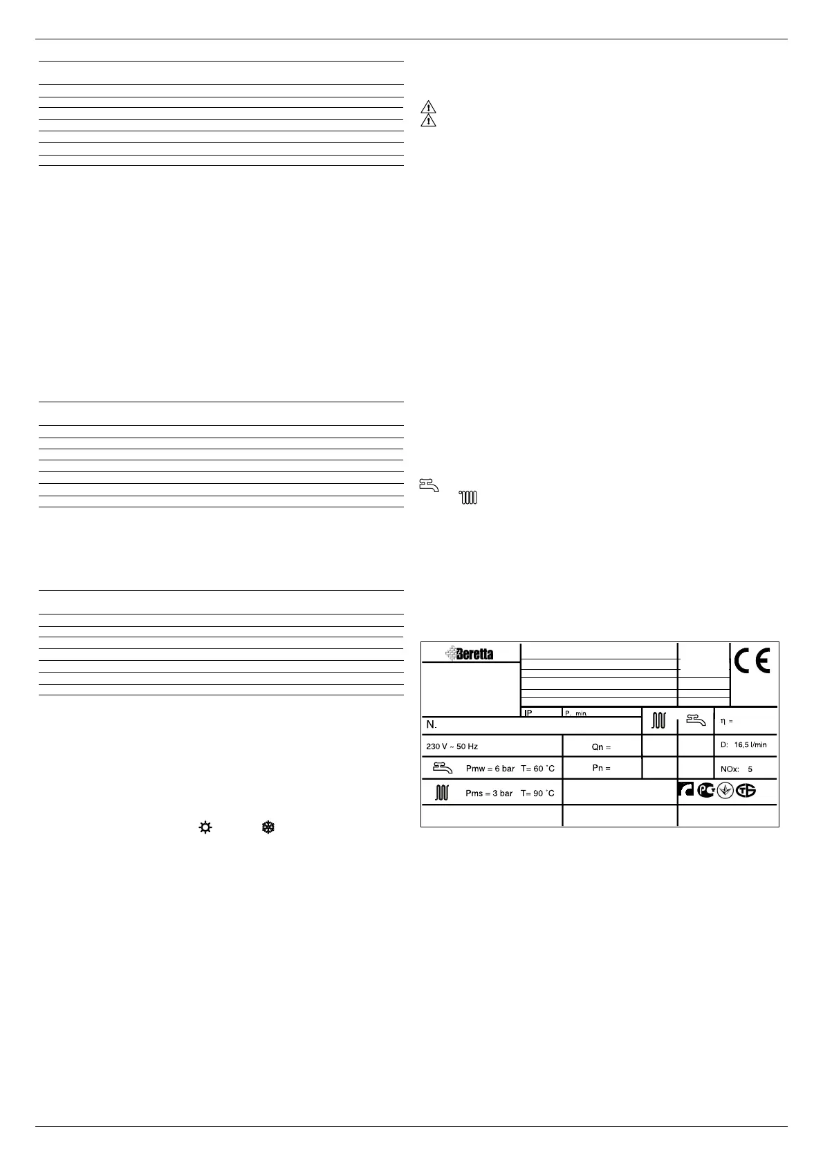
17 - SERIAL NUMBER PLATE
DHW operation
CH operation
Qn nominal capacity
Pn nominal power
IP protection level
P. min minimum pressure
Pmw DHW maximum pressure
Pms CH maximum pressure
T temperature
η working efficiency
D specific capacity
NOx NOx value class
Condensing boiler
Gas type
Gas
category

 Loading...