Mynute Green E C.S.I.
7
Twin pipes (Ø 80 mm) (Fig. 15)
The twin pipes can face in the direction most suitable for installation
requirements.
For installation, follow the instructions supplied with the specific ac-
cessory kit for condensation boilers.
Arrange the flue gas discharge pipe so it slopes by 3° towards
the boiler.
The boiler automatically adapts the purging to the type of in-
stallation and the length of the pipes. Do not obstruct or choke
the pipes in any way.
For the maximum length indications of the individual pipe see
the graphics (fig. 16).
The use of longer pipes reduces the boiler output.
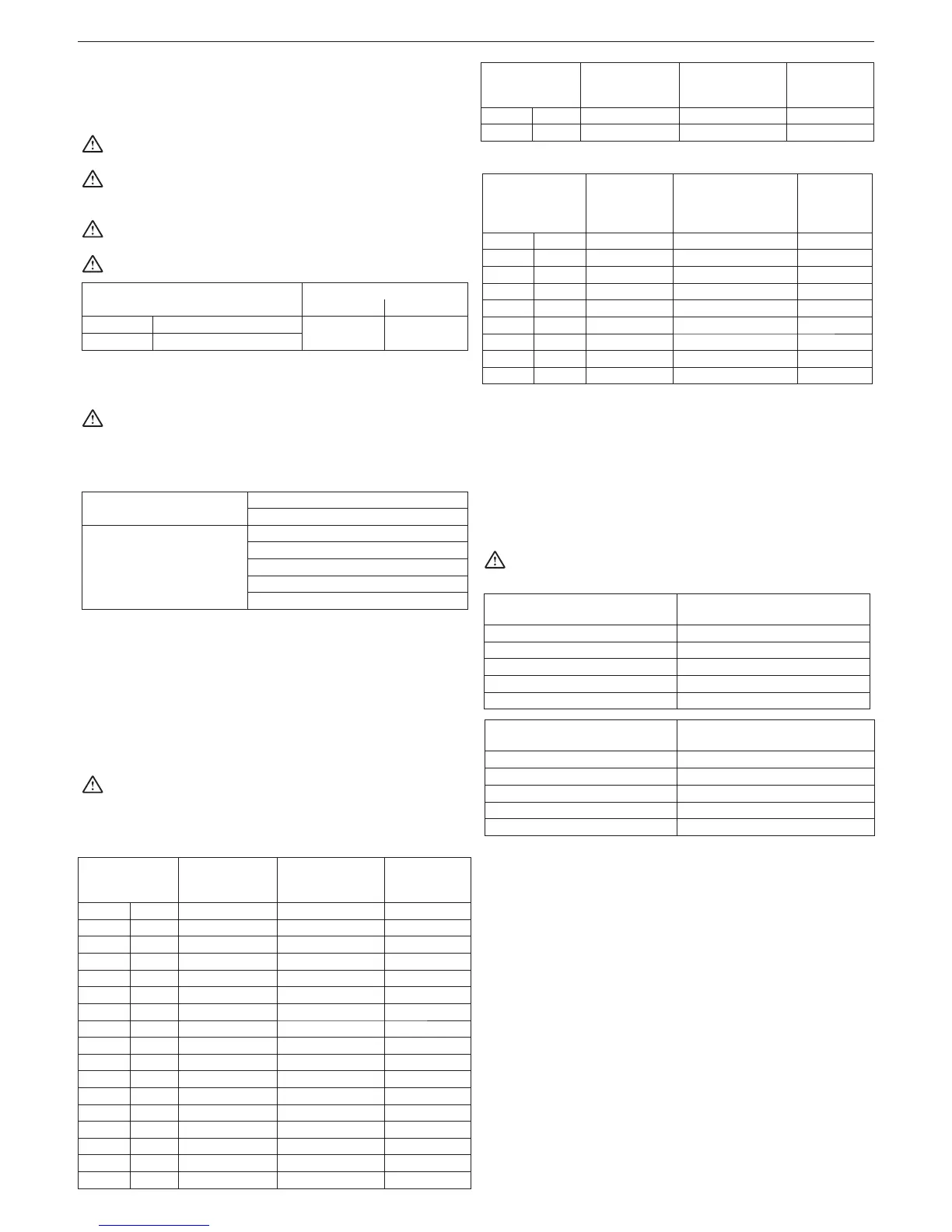
Maximum straight length
of twin pipe Ø 80 mm
Pressure loss
45° curve 90° curve
25 C.S.I. 53+53 m
1 m 1.5 m
30 C.S.I. 42+42 m
Ø 80 twin pipes with Ø 50 and 60 pipework (Fig. 17)
The characteristics of the boiler allow the Ø 80 flue gas discharge
pipe to be connected to the Ø 50 or 60 range of pipework.
For the pipework we recommend carrying out a design calcula-
tion in order to comply with the applicable prevailing standards.
The allowed base configurations are indicated in the table.
Base pipe configuration table (*)
Air suction 1 90° ø 80 curve
4.5 m ø 80 pipe
Flue gas exhaust 1 90° ø 80 curve
4.5 m ø 80 pipe
Reductio
n from ø 80 to ø 50 or ø 80 to ø 60
flue base curve 90° ø 50 or ø 60
for pipework pipe lengths see the table
(*) Use the plastic (PP) flue accessory systems for condensing boil-
ers that can be found on the residential catalogue price list, ø 50 H1
class and ø 60 P1 class
The boilers come from the factory calibrated to:
- 25 C.S.I.: 4,700 r.p.m. and maximum length reachable is 11 m for
the ø 60 pipe and
1 m for the ø 50 pipe
- 30 C.S.I.: 5,600 r.p.m. and maximum length reachable is 14 m for
the ø 60 pipe and
2 m for the ø 50 pipe
If you need to reach greater lengths compensate for the pressure
drop with an increase of the number of fan rotations as shown in the
adjustments table in order to guarantee the rated heat input.
The minimum calibration must not be modified.
If the prevailing value is greater than 200 Pa the law requires the use
of H1 pressure class flue accessories
Mynute Green E 25 C.S.I. adjustments table
Maximum number
of fan rotations
(rpm)
Ø 50 pipework pipes
maximum length
Ø 60 pipework pipes
maximum length
ΔP at the boiler
output with
max length (°)
DHW CH
mmPA
4700 3900 1
11 90
4800 4000 4
16 120
4900 4100 6
22 150
5000 4200 8
28 180
5100 4300 10
31 (*) 200
5200 4400 14
- 255
5300 4500 17
- 295
5400 4600 20
- 338
5500 4700 23
- 375
5600 4800 26
- 410
5700 4900 28
- 445
5800 5000 32
- 485
5900 5100 35
- 535
6000 5200 38
- 575
6100 5300 41
- 613
6200 5400 44
650
Maximum number
of fan rotations
(rpm)
Ø 50 pipework pipes
maximum length
Ø 60 pipework pipes
maximum length
ΔP at the boiler
output with
max length (°)
DHW CH
mmPA
6300 5500 49
710
Mynute Green E 30 C.S.I. adjustments table
Fan rotations
maximum number
of fan rotations
(rpm)
Ø 50 pipework
pipes
Maximum length
Ø 60 pipework pipes
Maximum length
ΔP at the
boiler output
with max
length (°
)
DHW CH
mmPa
5600 4700 2
14 145
5700 4800 4
19 183
5800 4900 5
21 (*) 200
5900 5000 8
- 255
6000 5100 11
- 295
6100 5200 13
- 330
6200 5300 15 377
6300 5400 19 440
(*) Compatible length with P1 class pipes
NOTE
If p
ipes different than those in the Beretta catalogue are used you must
see the ΔP values on the above tables to calculate the maximum length
of the pipes.
The Ø 60 and Ø 50 configurations have experimental, laboratory checked
data.
In the event of installations other than those indicated in the “base
configurations” and “adjustments” table, see the equivalent Ø 80 - Ø
60 or Ø 50 linear lengths shown below.
In any case the maximum lengths declared in the booklet are
guaranteed and it is essential that they are not exceeded.
Ø 60 component
Linear equivalent in
metres Ø 80 (m)
45° Ø 60 curve 5
90° Ø 60 curve 8
0.5 m Ø 60 extension 2.5
1.0 m Ø 60 extension 5.5
2.0 m Ø 60 extension 12
Ø 50 COMPONENT Linear equivalent in
metres Ø 80 (m)
45° Ø 50 curve
12,3
90° Ø 50 curve 19,6
0.5 m Ø 50 extension 6,1
1.0 m Ø 50 extension 13,5
2.0 m Ø 560 extension 29,5
3.11 Installation on collective flues in positive pressure
The collective flue is a gas discharge system suitable for collecting
and expelling the combustion products of several appliances in-
stalled on several floors of a building (fig. 18).
The collective flues in positive pressure can be used only for type C
condensing appliances. Consequently the B53P/B23P configuration
is not permitted.
Installation of the boiler on collective flues in pressure is permitted
only at G20 using a specific check valve, supplied as an accessory.
See the related instructions for the assembly procedure.
The boiler is sized to operate correctly up to a maximum internal
pressure of the smoke pipe no higher than the value shown in the
multigas table.
Complete the check valve assembly operations and proceed with
adjustment of the number of fan rotations as shown in the multigas
table.
Ensure that the air suction pipes and combustion product outlet are
airtight.
Installation of the check valve (fig. 19) requires the application of the
ATTENTION label that comes with the same accessory on a visible
part of the boiler shell. Applying the label is essential for safety during
maintenance or replacement of the boiler and/or the collective flue.
 Loading...