EasyManua.ls Logo

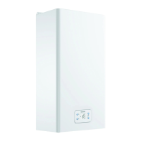
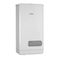
Beretta Mynute S 24 C.S.I. User Manual

Beretta Mynute S 24 C.S.I.
144 pages
To Next Page IconTo Next Page
Page #1 background imageLoading...
Page #1 background image
EN
INSTALLER AND USER MANUAL
ES
INSTRUCCIONES DE INSTALACIÓN Y USO
PT
INSTRUÇÕES PARA INSTALAÇÃO E USO
HU
TELEPÍTÉSI ÉS HASZNÁLATI KÉZIKÖNYV
RO
MANUAL DE INSTALARE ŞI UTILIZARE
DE
INSTALLATIONS- UND BEDIENUNGSANLEITUNG
SL
PRIROČNIK ZA MONTAŽO IN UPORABO
MANUEL D’INSTALLATION ET D’UTILISATION
F
Mynute S 24 C.S.I.
Mynute S 28 C.S.I.
Mynute S 35 C.S.I.
Mynute S 24 C.A.I.
Mynute S 28 C.A.I.
Mynute S 28 R.S.I.
Mynute S 35 R.S.I.
Question and Answer IconNeed help?

Do you have a question about the Beretta Mynute S 24 C.S.I. and is the answer not in the manual?

Beretta Mynute S 24 C.S.I. Specifications

General IconGeneral
Heat Output (kW)24
Efficiency ClassA
ColorWhite
Gas TypeNatural Gas / LPG
Power Supply230V
Maximum Flow Rate11.4 liters/min

Summary

General Safety Devices and Warnings

Boiler Installation, Maintenance, and Gas Leak Safety

Emphasizes professional installation, maintenance, and gas leak safety precautions.

Boiler Description and Safety Features

Installation Regulations

Installation Requirements: Position, Distances, and Connections

Specifies required placement, ventilation, clearances, mounting, and hydraulic connections.

Pre-Installation Checks and Anti-Freeze System

Outlines essential pre-installation steps and the anti-freeze system.

Gas Connection and Fumes Exhaust Systems

System Filling and Emptying Procedures

Ignition and Operation Modes

Preliminary Checks, Ignition, and Mode Selection

Lists pre-start checks, ignition steps, and mode selection for different models.

Temperature Adjustments and S.A.R.A. System

Explains temperature adjustments, pre-heating, S.A.R.A. system, and switching off.

Light Signals, Fault Codes, and Adjustments

Fault Handling and Power Adjustments

Guides on fault resolution and adjusting maximum power/DHW.

Gas Conversion and Maintenance Procedures

Combustion Parameter Checks

Details how to check and analyze combustion parameters.

User Safety Guidelines

Ignition and Switching Off Procedures

Ignition, Mode Selection, and Temperature Settings

Explains ignition, mode selection, and temperature settings.

Boiler Switching Off Procedures

Provides instructions for temporarily and long-term switching off the boiler.

Boiler Status Signals and Fault Handling

Restoring Operation and Resolving Faults

Guides on resetting alarms and resolving specific faults.

Technical Data (C.S.I. Models)

Technical Data (C.A.I. / R.S.I. Models)

Technical Data (Continued)

Technical Data (Gas and Flow Rates)

Technical Data (Gas and Flow Rates Continued)

Control Panel Overview and Icons (EN/F/ES/PT)

Control Panel Components

Describes the main parts of the control panel.

Icon Descriptions

Explains the meaning of various icons displayed on the control panel.

Control Panel Overview and Icons (HU/RO/DE/SL)

Control Panel Components

Describes the main parts of the control panel.

Icon Descriptions

Explains the meaning of various icons displayed on the control panel.

Boiler Functional Elements (EN/F/ES)

Boiler Functional Elements (PT/HU/RO/DE/SL)

Hydraulic Circuit Diagrams (Multilingual)

Serial Number Plate Information (Multilingual)

Room Thermostat Connection (Multilingual)

Safety Warnings for Thermostat Connection

Provides a critical warning regarding low voltage safety for thermostat connections.

Terminal Connections for Thermostat and Related Components

Explains specific terminal connections for thermostat and related components.

Electrical Connections and Polarisation (EN/F/ES)

Polarisation and Terminal Identification

Identifies key terminals and jumpers for electrical connections.

Control Card (MP) and Potentiometers

Describes the main control card and potentiometers for settings.

Electrical Connections and Polarisation (PT/HU/RO/DE/SL)

Circulator Residual Head (Multilingual)

Circulator Speed Settings

Refers to the different speed settings of the circulator.

Installation Guidelines and Component Identification

Indoor Installation Procedures

Describes the process and considerations for indoor boiler installation.

Terminal Connections (B, C)

Explains specific terminal connections for Fuse, Supply T.A., and Room Thermostat.

Component Identification for Adjustments

Adjustment Components Identification

Identifies compensation tap, pressure connections, safety cap, adjustment nuts, and spanners.

Calibration and Gas Selection Jumpers

JP1/JP2/JP3 Jumper Functions

Details the specific functions of JP1, JP2, and JP3 jumpers.

Heating Calibration Procedures

MIN Heating Calibration

Details the MIN heating calibration procedure.

MAX Heating Calibration

Details the MAX heating calibration procedure.
Related product manuals