7 Switching Amongst Tariffs
Hardware Controlled
Tariff inputs Ta and Tb are each connected with refer-
ence to Tn.
Level 0: < 12 V
Level 1: > 45 V (max. 265 V permissible!)
Software Controlled (not included in MID scope of approval)
In the case of meters with bus connection, four further
tariffs can be selected (software controlled).
8 Overview of Bus Systems
–
LON-Bus
–M-Bus
– TCP/IP (BacNet IP/Modbus TCP)
–Modbus RTU
Interface descriptions for energy meters with bus connection
can be found on the Internet at www.berg-energie.de.
9 Error Messages – Reset
Display
If an error occurs, the respective error code and active
energy or instantaneous power are displayed alter-
nately.
LOVoLt error
In case of LOVoLt error (phase voltages too low), back-
ground illumination, and if applicable the bus connec-
tion, are deactivated. The load profile (feature load pro-
file) cannot be viewed as long as the error is pending.
10 Repair and Recalibration
Note for Test Laboratories
Direct measuring meter: Testing is only possible with
source which supply currents superimposed on volt-
ages.
Calibration Display
Display of energy values with increased resolution can
be selected for testing or calibration purposes.
➭ Press and hold the ENTER key once to this end. The
firmware version is displayed with a red back-
ground.
➭ Press the UP key twice. The calibration display ap-
pears with a pink background.
Resolution depending on display, see section 6.2.
Recalibration can be conducted at any time by a feder-
ally approved test laboratory (e. g. EB-8) (see repair and
service address on the back of the folder).
Calibration capability is valid for 8 years in Germany.
11 Manufacturer’s Guarantee
The energy meters are guaranteed for a period of 3
years after shipment. The manufacturer’s guarantee
covers materials and workmanship. Damages resulting
from use for any other than the intended purpose or
operating errors, as well as any and all consequential
damages, are excluded.
12 Ambient Conditions
13 Return and Environmentally Sound Disposal
The BME meter is a category 9 product (monitoring and
control instrument) in accordance with ElektroG (Ger-
man electrical and electronic device law). This device is
subject to the RoHS directive.
We identify our electrical and electronic
devices in accordance with WEEE 2012/19/EU
and ElektroG using the symbol shown at the
right per DIN EN 50419.
These devices may not be disposed of with the trash.
Please contact our service department regarding the
return of old devices.
14 Declaration of Conformity, Direct Meter 15 Declaration of Conformity, Transformer Meter
Tariff Input Tb Ta
Tariff 1 0 0
Tariff 2 0 1
Tariff 3 1 0
Tariff 4 1 1
Error Code Meaning Cause / Remedy
0L0volt
Phase voltage < 75% Check connection
0VHi1
Maximum value for U1
exceeded
Check connection
0 VHi 2
Maximum value for U2
exceeded
Check connection
0 VHi3
Maximum value for U3
exceeded
Check connection
1Hi1
Maximum value for I1
exceeded
Check connection
1Hi2
Maximum value for I2
exceeded
Check connection
1Hi3
Maximum value for I3
exceeded
Check connection
0SYnc
Frequency measuring
error
Meter connected to direct
voltage
0C0m
Interface error
Check connection
EnErgY
Meter defective
Send device to
repair service
0cALib
Balancing required
0
AnALog
DC offset too high
Operating temperature range –25 ... +55 °C
Storage temperature range –25 ... +70 °C
Relative humidity < 75% annual average
Elevation to 2000 m
Deployment Indoors
mechanical classification M1
electromagnetical classification E2
Protection (built-in device) front panel: IP 51
Protection terminal area IP20
12345. 678
4567
kWh
W
1 n a
Calibration
Firmware
Normal display
Pulse rate
Pulse Duration
Feature V2/V4
Feature V2/V4
12345. 678
678
kVArh
VAr
1
n R
CT
VT
112345
.
6
7
8
4567
kWh
W
0 u t a-
12345
.
6
7
8
678
kVArh
VAr
0 u t R-
12345
.
6
7
8
1
2345
.
678
kWh
kVArh
1 n
Reactive energy import, total
1 123
4
2 1
234
W
3 1
234
Active power / phase
1 230
.
0
2
230
.
4
V
3 230
.
4
Phase voltages
12345
.
6
7
8
1
2345
.
678
kWh
kVArh
0 u t
12345
.
6
7
8
1
2345
.
678
kWh
kVArh
t1 : 1 n
12345
.
6
7
8
1
2345
.
678
kWh
kVArh
t1 : 0 u t
Export, total
Active energy import, total
Tariff (T1)
Tariff (T1)
Power displays
1 1234
2
1234
VAr
3 1234
1 1 234
2
1234
VA
3 1234
1234
1234
VA
VAr
1234
Reactive power / phase
Apparent power / phase
Total power
Mains monitor
12 400
.
4
23
400
.
4
V
31 : 400
.
4
Line-to-line voltage
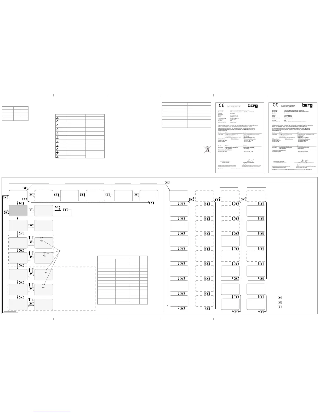
Switching Between Active and Reactive Energy – Display Tests – Calibration Display – Setting Transformer and S0 Interface Parameters Switching Amongst Tariffs, Active and Reactive Energy, as well as Power Displays and Mains Monitor, Optional Display of the Load Profile
1
Total active power (kW) appears at auxiliary display 2
2
Not approved for billing purposes in Switzerland
Measuring Function
Feature
Measured Quantity Accuracy M3
2
Active energy (kWh)
1
EP1...EP8, EPtot ± 1%
•
Reactive energy (kVArh)
EQ1...EQ8, EQtot
±2%
•
Star voltage (V) U1
N
, U2
N
, U3
N
0.5% ±1 d
•
Delta voltage (V) U12, U23, U13 0.5% ± 1 d
•
Current per phase (A) I1, I2, I3 0.5% ±1 d
•
N conductor current (A) I
N
1%
±
1 d, typ.
•
Active power (kW) P1, P2, P3, Ptot 1% ±1 d
•
Reactive energy (kVAr) Q1, Q2, Q3, Qtot 1% ± 1 d
•
Apparent power (kVA) S1, S2, S3, Stot 1% ± 1 d
•
Power factor
(cos phi)
PF1, PF2, PF3,
PFtot
1% ±1 d
•
Frequency (Hz) f 0.05% ± 1 d
•
RMS distortion value THD U1, U2, U3
•
THD I1, I2, I3
•
Blinking cursor
Identifies the current entry position. Position
selection via ENTER.
The value at the cursor position can be
changed with the UP key (upward arrow).
Abbreviations
ct Transformation ratio, current
I
N
N conductor current (calculated)
SØ SØ pulse output
THD Distortion component (for voltage and current)
vt Transformation ratio, voltage
Features
M3 Multifunctional variant:
measurement of U, I, P, Q, S, PF, f, THD, In, reactive energy
Q1 Programmable transformation ratios
V2 Programmable SØ
W1 ... 7 Bus connections
Keys
ENTER key (press briefly)
ENTER key (press and hold)
UP key (press briefly)
Pulse source
4 pulse sources for pulse outputs SØ1 and SØ2:
– Active energy import (+) kWh or export – kWh
– Reactive energy import (+) kVAr or export – kVAr
2 states: SØ switch “
C l o s e d” or “0 p e n”
Operating Overview
W
Feature V2/V4
Transformation ratios (Transformer Meter only)
Feature bus connection: T5 ... T8
Active energy import
Active energy export
Fixed display and illumination – live values
12345
.
6
7
8
1
2345
.
678
kWh
kVArh
1 n
Active energy import, total
12345
.
6
7
8
1
2345
.
678
kWh
kVArh
0 u t
Active energy export, total
2 additional
Display test
Pulse rate
Number of pulses to be
read out per kWh
Pulse duration
Duration of the pulse for the on state or the high
value: at least 30 ms, e.g. 70 ms in case of
processing problems
version
1 .0 0
2345. 6789
1234.5678
kWh
kWh
1234
W
2345. 6789
1234.5678
kWh
kWh
hold
10000
c t
10000
c t
set
1000
u t
1000
u t
set
50 1000
per kWh
50 1000
per kWh
set
50 0.100
sec
50 0
.
100
sec
set
50 srC1/2
+ / – kWh
50 srC1/2
+ / – kWh
set
SØ pulse output**
test patterns
8888:88:88
8888:88:88
kWh
kWh
88:88:88
Information for manufacturing
All Tariffs *
Active tariff (here T1)
Reactive energy import, total Reactive energy export, total
Reactive energy, capacitive
Reactive power, capacitive
Active energy export
Active power export
Reactive energy, inductive
Reactive power, inductive
Active energy import
Active power import
* Max. 4 tariffs with S0
or 8 tariffs with bus
T1 T1 T1 T1 T1T3 T1T3
T2T4 T2T4
long
** See corresponding interface description for additional menus in case of bus connections.
Transformer Meter: Programmable CT, VT
T1T3
T1T3
T1
T1
pf1 : 1
.
00
2
: 1
.
00
3 : 1
.
00
Power factor / phase
pf : 1
.
00
50
.
00
H
z
Power factor
T1
T1
T1
T1
T1
T1
1 1
.
234
2
1
.
234
A
3 1
.
234
1n1
.
234 A
50
.
00
h
z
kW
dv1 : 0
.
120
2
: 0
.
042
3 : 0
.
050
THD U1, U2, U3
d11 : 0
.
476
2
: 0
.
120
3 : 0
.
092
THD I1, I2, I3
T1
T1
T1
T1
T1
T1
Phase currents
Line frequency
4-wire only4-wire only
4-wire only4-wire only4-wire only4-wire only
Active Tariff (here T1)
3/4-wire
2-wire
1234
1234
VA
VAr
1234
Apparent/reactive/active power
W
pf : 1
.
00
50
.
00
H
z
Power factor
T1
T1
123
.
4
1
.
234
V
A
50
.
00
H
z
Voltage/current/frequency
dv : 0
.
028
d1
: 0
.
082
THD U, I
T1
T1
12345
.
6
7
8
1
2345
.
678
kWh
kVArh
t 2 : 1 n
12345
.
6
7
8
1
2345
.
678
kWh
kVArh
t 2 : 0 u t
Tariff (T2)
Tariff (T2)
T1
T1
12345
.
6
7
8
1
2345
.
678
kWh
kVArh
t 3 : 1 n
12345
.
6
7
8
1
2345
.
678
kWh
kVArh
t 3 : 0 u t
Tariff (T3)
Tariff (T3)
T1
T1
long
→
→
→
→
→
12345
.
6
7
8
1
2345
.
678
kWh
kVArh
t1 : 1 n
Reactive energy
12345
.
6
7
8
1
2345
.
678
kWh
kVArh
t1 : 0 u t
12345
.
6
7
8
1
2345
.
678
kWh
kVArh
t 2 : 1 n
12345
.
6
7
8
1
2345
.
678
kWh
kVArh
t 2 : 0 u t
Tariff (T1)
Active energy
Tariff (T2)
Tariff (T2)
Feature bus connection: T5 ... T8
T1
T1
T1
T1
12345
.
6
7
8
1
2345
.
678
kWh
kVArh
t 3 : 1 n
12345
.
6
7
8
1
2345
.
678
kWh
kVArh
t 3 : 0 u t
Tariff (T3)
Tariff (T3)
T1
T1
12345
.
6
7
8
1
2345
.
678
kWh
kVArh
t 4 : 1 n
12345
.
6
7
8
1
2345
.
678
kWh
kVArh
t 4 : 0 u t
Tariff (T4)
Tariff (T4)
T1
T1
T2T4
T2T4
Q1: secondary calibrated
Tariff (T1)
N current (4-wire only)
display
1.8.1
3.8.1
2.8.1
4.8.1
1.8.2
3.8.2
2.8.2
4.8.2
1.8.3
3.8.3
2.8.3
4.8.3
1.8.4
3.8.4
2.8.4
4.8.4
OBIS
1.8.1
3.8.1
2.8.1
4.8.1
1.8.2
3.8.2
2.8.2
4.8.2
1.8.3
3.8.3
2.8.3
4.8.3
1.8.0
3.8.0
2.8.0
4.8.0
 Loading...