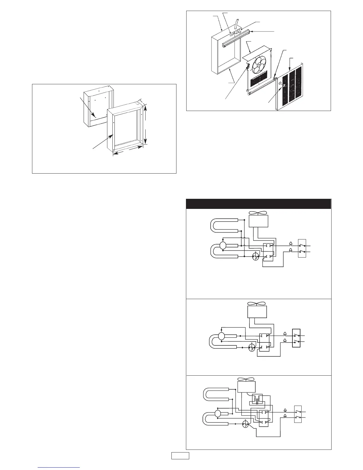
Installation of Back Box with Optional
Surface-Mounting Frame (See Figure 3)
1. Secure back box to wall with knockouts in upper right
hand corner using screws and anchors.
2. Hang the surface-mounting frame on the back box.
Ensure that the back edge of the surface-mounting frame
is flush against the wall.
NOTE: If heater is located in a high traffic area, where it may
be subjected to vandalism or abuse, take extreme care to see
that the box is firmly attached to the wall.
3. Power Supply Wiring
NOTE: Wiring Compartment Volume - 119in
3
(1950cm
3
).
a. Run a power supply cable into the area to the upper
right corner of the mounting frame. Arrangement of
wiring to this point must be in accordance with National
and Local codes. Refer to specifications on page 2 for
proper wire size.
NOTE: If the wiring is to run through the wall, cut a hole
in the area of the top of the back box. Run the supply wire
through this hole. Then remove the “knockout” from the
top of the box and proceed to step C.
b. Remove the “knockout” on the top side of the frame.
c. Remove disconnect switch bracket by loosening the
two screws on the right side.
d. Feed the power supply cable through the frame allow-
ing 6" (152mm) of lead to remain inside the back box
(using cable clamp, connector, or other suitable
strain relief).
e. Secure the power supply cable to the back box
(using cable clamp, connector, or other suitable strain
relief) allowing 6" (152mm) of lead to remain inside the
inner housing.
f. Connect supply wires to blue wires of disconnect
switch using wiring connectors (see wiring diagram,
next column).
g. Ground the back box by connecting the supply ground
leadwire to the green ground screw located in the
inside top of the housing.
h. Secure disconnect switch bracket in place.
Installation of Heater Assembly and Grille
After back box is completely installed and no further con-
struction dirt is expected, clean debris from back box, remove
heater assembly from its carton, then refer to Figure 4 and
proceed as follows:
1. Insert the heater assembly into wall housing, placing
the four mounting holes (with key-hole slots) over the
screws in the housing. Tighten all screws securely.
2. If surface-mounting frame is used, ensure that the
frame is even with all four heater assembly tabs before
tightening screws.
3. Connect the two disconnected switch wires to the heat-
control switch (thermostat) leads using wirenuts (see
wiring diagram, next column). After connection, push
wires back into the opening.
4. Turn thermostat to the extreme counterclockwise
position.
5. Push disconnect switch into ON position.
6. Install (2) plastic covers on back box as follows: (See Fig. 4)
NOTE: Both top and bottom plastic covers are identical.
• TOP - Align the screw bosses on the back of the plastic
cover with the second hole down from the top of the
back box and attach it with the two screws provided.
• BOTTOM - Align the screw bosses on the back of the
other plastic cover with holes at the bottom of the back
box that are just above the fan deck mounting screws
and attach it with two screws provided.
7. Remount the wire compartment cover. Install the front
cover by hooking the (2) tabs on the one side then rotat-
ing the front cover into place making sure that all four tabs
are snapped onto the front cover.
8. Fit the thermostat knob onto the thermostat shaft and
push into place.
Fig. 3: Optional Surface Mounting Frame Installation
Fig. 4
MOUNT BACK BOX
TO WALL USING
REAR MOUNTING
HOLES.
HANG FRAME
ON BACK BOX.
15-5/32 "
(385mm)
19"
(482mm)
3-13/16"
(97mm)
THERMOSTAT KNOB
FRONT COVER
PLASTIC
COVER
PLASTIC COVER
POWER LEADS
BACK BOX
INNER FRAME
ASSEMBLY
RECESS WALL
HOUSING
DISCONNECT
SWITCH
THERMOSTAT
 Loading...