Do you have a question about the BERMAD 700 Series and is the answer not in the manual?
Initial steps for de-pressurizing the system and preparing for potentiometer installation.
Details on cleaning, inspecting parts, and assembling the indicator rod and cover plug.
Guidelines for assembling the potentiometer, checking connections, and preparing for calibration.
Steps to calibrate the potentiometer to 4mA (closed) and 20mA (open) settings.
This document outlines the installation and calibration procedures for the Celesco Potentiometer, specifically the RT9420 model, when integrated with Bermad 700 Series Control Valves. This potentiometer is designed to provide a precise electrical signal (4-20 mA) corresponding to the valve's position, allowing for remote monitoring and control of the valve's opening and closing.
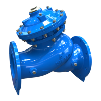
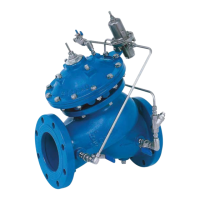
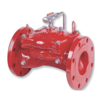
The Celesco Potentiometer acts as a position sensor for Bermad 700 Series Control Valves, which range in size from 1-1/2 inches to 32 inches. Its primary function is to translate the mechanical movement of the valve stem into a proportional electrical current output. This 4-20 mA signal is a standard in industrial control systems, enabling the valve's position to be accurately read by a Programmable Logic Controller (PLC), Distributed Control System (DCS), or other monitoring equipment. The potentiometer is mounted externally on the valve cover and connects to the valve's internal indicator rod, which moves with the valve stem. As the valve opens or closes, the indicator rod rotates the potentiometer's shaft, changing its electrical resistance and, consequently, the current output. A 4 mA signal typically indicates a fully closed valve (no-stroke position), while a 20 mA signal signifies a fully open valve (full stroke position). This continuous feedback is crucial for automated processes that require precise valve control and status verification. The system is designed to operate on a DC current, requiring a voltage supply between 12 VDC and 40 VDC.
The installation process for the RT9420 potentiometer involves several key steps to ensure proper function and accurate calibration. Before beginning, it is critical to depressurize and isolate the main valve from the system to ensure safety and allow for proper access. This involves shutting off upstream and downstream gate/butterfly valves and all cock valves feeding the control loop. Adequate space around the valve cover is necessary for mounting the potentiometer and its bracket, as well as for accessing the zero ('Z') and span ('S') adjustment screws used for fine-tuning.
The potentiometer assembly includes a bracket (8), a lever arm (3), and a collar (8) that rides on the indicator rod (48). The lever arm connects to the potentiometer shaft (1A), translating the linear movement of the indicator rod into rotational movement for the potentiometer. The collar's position along the indicator rod determines the range of the valve's stroke that the potentiometer will measure. The installation requires careful attention to ensure the lever arm roller does not bind within the collar throughout the valve's full stroke. The document provides a chart detailing the measured valve stroke for various valve sizes, which is essential for setting the potentiometer's span correctly.
Calibration is a critical step, performed using a multi-meter capable of measuring DC milliamps (4-20 mA). The calibration process involves setting the low-end (4 mA) and high-end (20 mA) signals. For calibration, two 9-volt alkaline batteries connected in series are recommended as a power source. The 'Z' adjustment screw is used to fine-tune the 4 mA reading when the valve is in its fully closed position, while the 'S' adjustment screw is used to fine-tune the 20 mA reading when the valve is at its full stroke position. The process emphasizes finding a "sweet-spot" for the potentiometer shaft rotation to ensure the full span of the valve's movement is captured without binding or stripping adjustment screws. The document also highlights the importance of correct polarity when connecting the batteries and multi-meter to avoid erroneous readings or damage.
Maintenance aspects are integrated into the installation and calibration procedures to ensure the longevity and accuracy of the potentiometer. Before installation, thorough cleaning of the cover plug hole and inspection of the indicator locknut (19) for corrosion or wear are recommended. If the locknut is loose, applying Loctite thread-lock compound and tightening it clockwise is advised. The document also suggests inspecting all fittings on the cover for discoloration, breaks, or leaks and replacing them if necessary. Cleaning cover taps with a wire bore brush and re-tapping with the proper NPT-tap is recommended, especially for valves in service for several years in aggressive water environments.
During assembly, proper lubrication of the o-rings (43, 59, 41) on the indicator cover plug (46) and indicator rod (48) is crucial to prevent damage and ensure smooth operation. The e-clip (44) must be correctly installed into the grooved recess of the indicator rod to secure it. The indicator rod (48) should spin freely within the indicator locknut (19) but should not be able to be pulled up or down, indicating a secure fit. If the rod moves vertically, the indicator cover plug should be removed for inspection, and if the issue persists, the indicator locknut (19) may need replacement.
The calibration process itself serves as a diagnostic tool. If achieving the 4 mA or 20 mA settings proves impossible, it prompts a re-evaluation of the installation steps, including checking for binding, verifying the potentiometer's "sweet-spot," and confirming the correct potentiometer model number for the specific valve size using the provided chart. Troubleshooting steps also include verifying the voltage output of the batteries and checking the multi-meter's functionality, including its internal fuse, if no mA readings are obtained. The document stresses the importance of using insulated alligator clips and, if necessary, appropriate gauge wire to prevent bare metal connections from touching conductive materials, which could lead to erroneous readings or damage. After calibration, the 'Z' and 'S' cover screws should be replaced and tightened to protect the fine-tuning adjustments.
| Type | Hydraulic Control Valve |
|---|---|
| Body Material | Ductile Iron |
| End Connection | Flanged, Grooved, Threaded |
| Operation | Hydraulic |
| Application | Irrigation, Fire Protection |
| Series | 700 Series |