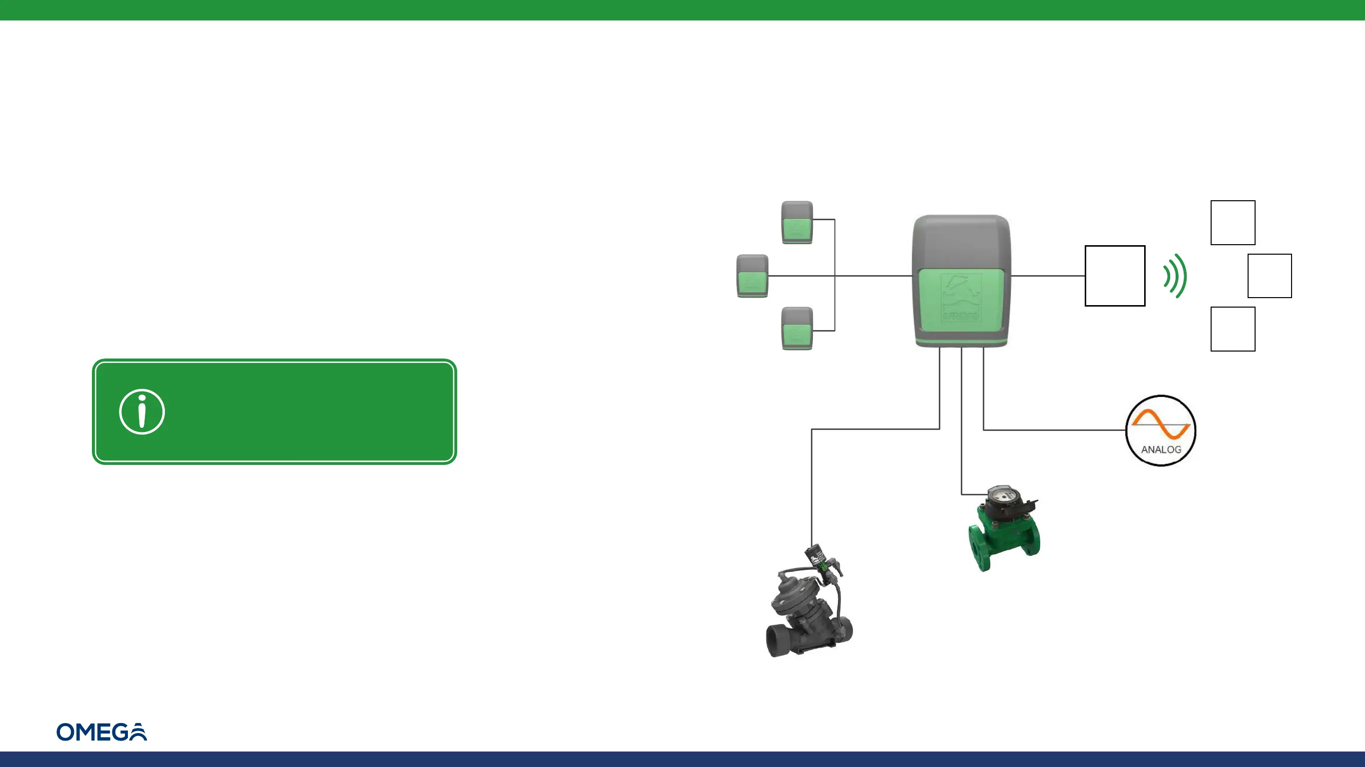
Introduction | Typical Connection Layout |
10
Omega | Installation and Operation Guide | Rev A | Doc P/N: PIEAE21-OMEGA
Typical Connection Layout
The following can connect to the Omega controller's connection
terminals (see Connecting Peripherals):
Latch output connection terminals:
▪ Latch solenoids - irrigation valves and master valve
▪ Latch relay - water pumps
Digital input connection terminals:
▪ Water meters
▪ Dry contact and open collector digital sensors
Analog input connection terminals:
▪ Analog sensors
Up to ten extension controllers –
total of 44 latch outputs, 44 digital
inputs, and 22 analog inputs
(RS models only)
RF
Gateway
RF
Remote
Unit
RF
Remote
Unit
RF
Remote
Unit
RS-485 RS-485
Tip: When installing open
collector sensors, verify the
polarity matches what is marked
on the Omega connector board
Up to five
latch outputs
Up to four
digital inputs
Up to two
analog inputs
Up to forty RF remote units
– total of 44 latch outputs, 4
digital inputs, and 2 analog
inputs (RS models only)
 Loading...