• 33 •
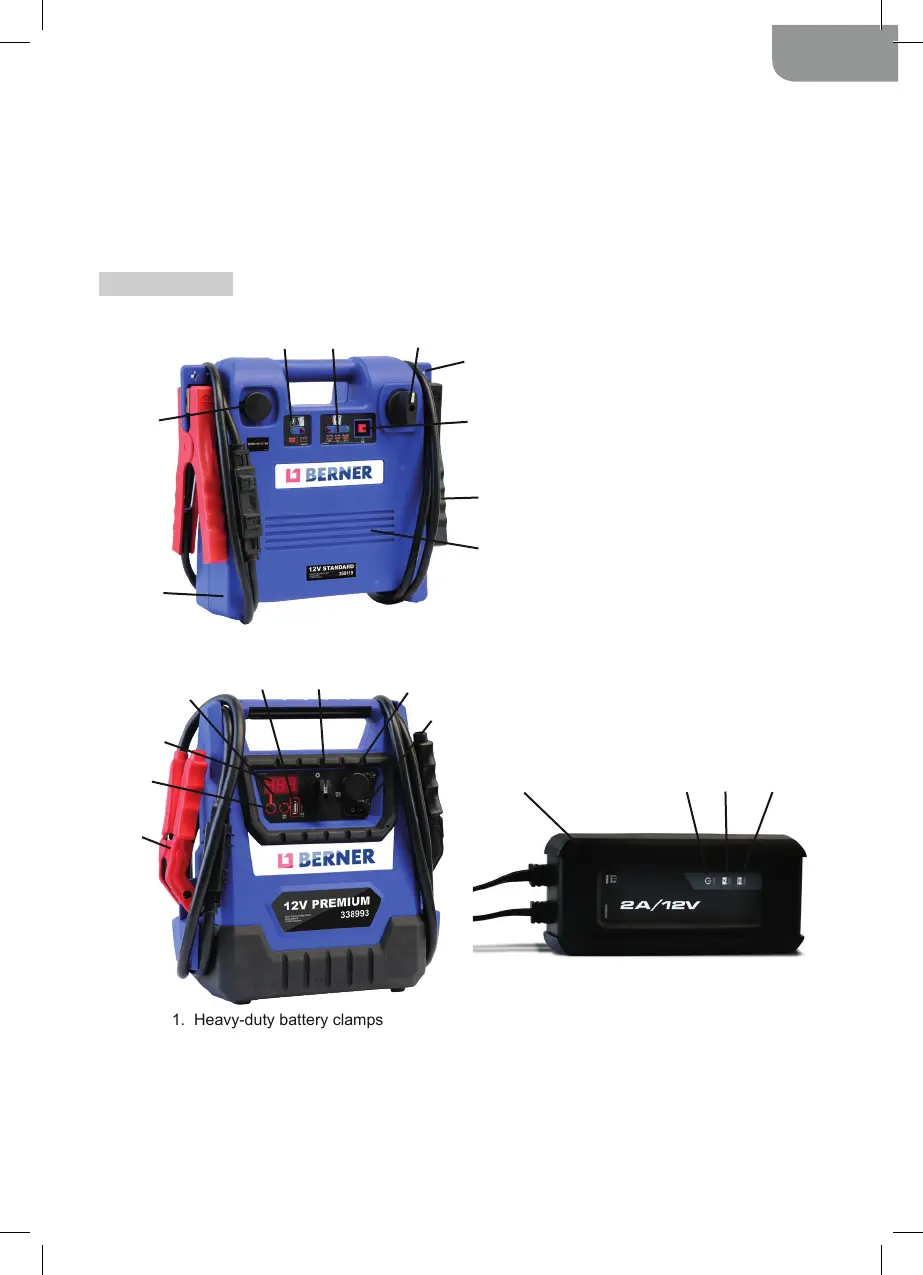
1. Heavy-duty battery clamps
2. Display button
3. Digital display
4. USB button
5. USB Port
6. Booster ON/OFF switch – 0
or 12V position for Model 338993 / 0
or 12V or 24V position for Model 406736
7. 12V DC socket
8. 12V DC charge port
9. 12V-2A charger
10. Power LED
11. Charging status LED
12. Bad Battery LED
1. Durable polypropylene case
2. 12 Volt DC power outlet
3. Charging status LEDs
4. Internal battery status LEDs
5. ON/OFF switch
6. Clamp holder
7. Internal battery status push-button
8. Heavy-duty battery clamps
9 . P r o f e s s i o n a l - g r a d e , h i g h - o u t p u t A G M
battery
1
2
3
4 5
6
7
8
9
1
2
3
4
5
6
7
8
9 10 11 12
or engine block.
4.6. When disconnecting the booster, rst remove the clamp from the vehicle chassis, then remove
the clamp from the battery terminal, in that order.
4.7. In the rare event that the vehicle is positive-grounded, connect the NEGATIVE (BLACK) clamp from
the booster to the NEGATIVE (NEG, N, -) ungrounded post of the battery. Connect the POSITIVE
(RED) clamp to the vehicle chassis or engine block away from the battery. Do not connect the clamp
to the carburetor, fuel lines or sheet-metal body parts. Connect to a heavy gauge metal part of
the frame or engine block.
5. FEATURES
5.1. Booster 12V Standard (Model 369119)
5.2. Booster 12V Premium (Model 338993) and Booster 12/24V Uni (Model 406736)