4.00 FRONT PANEL FUNCTIONS
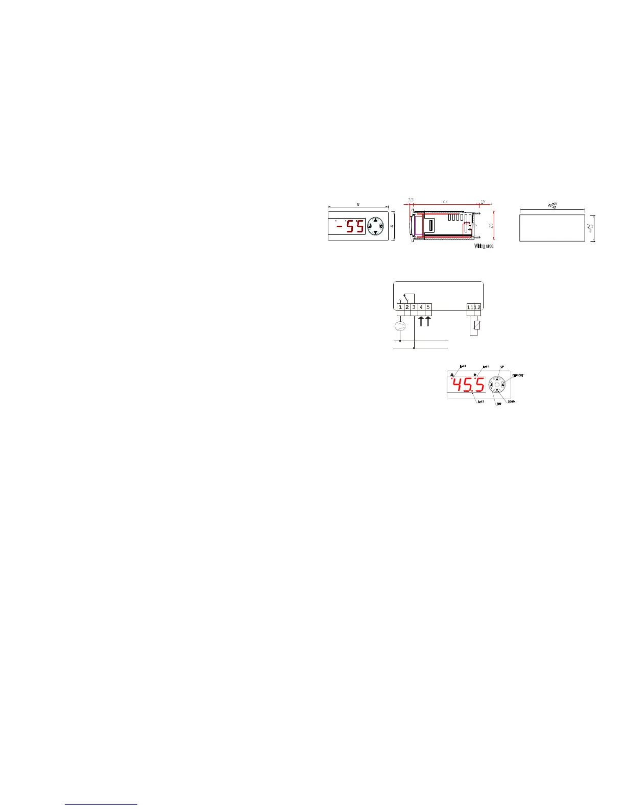
4.10 Front panel layout
(standard version RD31-60xx)
The display has tree digits available, of the seven segment type. During normal working it shows the value of the temperature, while in an alarm
condition it shows the proper indication as described in the «anomalies signaling» table.
Led 1 lights up while the compressor/heater is operating and led 3 during a defrost cycle. In program mode led 3 is blinking.
Note: if alarm is on, press the “6” key to switch off the optional internal buzzer.
4.30 READ / MODIFY FUNCTION OF THE SET POINT
1) Press “↵” and hold it for 3s, SEt is displayed;
2) Press “↵” to view the Set Point value, adjust it by using “5” or “6”;
3) Press “↵” to confirm the data, after 10s the controller will leave the set mode and the data will be stored in the memory.
WARNING: the instrument must not be reset before leaving the set mode, otherwise the new setting will be lost.
Note: it is only possible to choose values for the set point inside the «Los» and «His» range.
4.40 READ / MODIFY FUNCTION FOR THE PARAMETER MENU
1) Press “↵” and hold it for 10s, the code of the first variable “HyS” will appear;
2) Press “5” or “6”to scroll all the parameter codes;
3) While a code is displayed press “↵” to view its content, adjust it by pressing “5” or “6”;
4) Press “↵” to confirm the data, after 10s the controller will leave the set mode and the data will be stored in the memory.
WARNING: the instrument must not be reset before leaving the set mode, otherwise the new setting will be lost.
Note: the new values for time parameters will be active only after the start of the following time cycle.
4.50 HOW TO ACTIVATE MANUALLY A DEFROST CYCLE (only for RD31-50xx and RD31-60xx standard – not “OnOff”)
Press and hold for about 5s the “Defrost” key (the right-side pushbutton), the compressor output will switch off and the led 3 will lights on.
4.60 HOW TO SWITCH OFF AND ON MANUALLY THE CONTROLLER (only for RD31-xxxx “OnOff” version)
Instead of the “Defrost” key there is an “On/Off” function. Press and hold for 5s the right-side pushbutton, the controller will switch off (display and
output). Press again the right-side pushbutton to toggle on the controller, it will resume to measure and regulate the temperature.
The instrument can store or not on its memory the “Off status” as per order request. Memorizing the “Off status” the controller stays off also after a
power cut or blackout.
4.70 LOCK / UNLOCK KEYBOARD
Press and hold simultaneously SET and “6” for 10s, in order to lock and unlock the keyboard.
Code displayed for one second: Pof Locked Pon Unlocked
It is possible to change only the Set point value when the keyboard is locked.
We recommend to use wires of proper gauge, according to the power of the load; in any case do not exceed 2.5 mm
2
to avoid damage of the connector.
See the label on top of the instrument for the right power supply diagram connection.
The RD 31 based on the PD Program is a low-
Cycle defrost, specifically designed to control refrigerating
static units operating at positive temperatures.
This type of controller is particularly indicated, either for the
cal refrigeration units or for contractors /
installers. Applications span from refrigerated cabinets, to
displays, wine show cases, bottle coolers, chafing dish, etc.
The controller can support one input PTC type sensor and offers
the compressor/heater control in order to cool
down or to warm up something, simply changing the value of an
internal parameter.
The instrument can perform the OFF-
cycle defrost function by
shutting off the compressor at regular intervals time, which can
programmed from 1 to 99 hours.
On the RD31-50xx and RD31-
60xx standard version, the user has
the possibility to start/stop manually the defrost cycle, by pushing a
Available an On/Off version where the user can switch on and off
the controller by pushing the right side front panel key
controller can or cannot store the “off” status on its memory –
This new RD 31 Program controller can work at a decimal point
resolution in the range -9.9…+99.9 °C (°F) and
switches to unit resolution out of this range.
DISPLAY: 3 digit, 13.2 mm, high intensity red;
INPUTS: one PTC sensor, KTY81-121 semiconductor type;
opt: PTC 300 sensor, KTY84-130 (polarized);
opt: with 1 digital input N.O. contact;
MEASURING RANGE: -50 … +150 °C (-58 … +302 °F);
(-25 … +270 °C if PTC300 input);
ACCURACY AT 25°C: ±0.5°C (±0.9°F) + 1 digit;
RESOLUTION: 0.1°C (0.2°F) + 1 digit;
TIME ACCURACY: ±5%;
OUTPUTS (max 2): 1 SPDT 8 A, ½ hp 250 Vac relay;
opt. – 1 SPDT 16 A, 1 hp 250 Vac;
opt. – 1 SPST 30 A, 2 hp 250 Vac;
+ opt. 1 SPST alarm relay – 250 Vac 5A res. or buzzer;
POWER SUPPLY: 230 Vac ±10%, 50/60 Hz;
opt.: 115 Vac ±10%, 50/60 Hz; 12 Vac/dc ±10%;
switching 9..24Vac/dc.
ENVIRONMENTAL CONDITIONS:
-operating temperature: –5 … +50 °C;
-storage temperature: –20 … +70 °C;
-relative humidity: 30 … 90 % non condensing;
-no shocks or vibrations;
MECHANICAL DATA:
-rectangular hole panel mounting 70.5 x 28.5 mm;
-plastic housing self extinguishing type UL94V0;
- connections through screw terminal block for max 2.5mm
2
wire (or max 4mm
2
for rigid wire); max current 16 A (max
24 A if 2 hp relay is present).
-protection degree: IP64 for the frontal panel.
The installation must be done only by specialized personnel in according to the rules in force in the country where the controllers are used.
nt is conceived for controlling and regulation working not for safety function. It must be installed in a place protected from
extreme vibrations, impact, water, corrosive gases, and where temperature and moisture do not exceed the maximum rating levels in
in the specifications. The same directions are valid for the probe installation.
3.11 THE THERMOSTAT PROBE
The probe must be installed in a place protected from direct air flow particularly far from fans and doors, so a better average temperature
the room will be measured. The probe is not waterproof, it should be placed with its head upward, so that drops would not penetrate into the
bulb and damage the sensor. Maintain the length of the electrical wires as short as possible in order to keep th
e noise picked by them at low
level, otherwise a shielded wire will be needed, where the shield will be connected to the ground.
3.12 ELECTRICAL WIRING
We recommend to protect the power supply of the controller from electrical noise, spikes, and especiall
y from voltage surges and drops. This
can be easily done following these recommendations:
-
separate the power supply of the loads (compressor, heaters, fans, etc) from the power supply of the controller. This can alleviate problems
related to voltage dips that can arise during the switch-
on of the loads, that may interfere with the controller’s microprocessor causing
unexpected resets.
-the cables of the probes and the ones of the controller supply or the loads must be separated and not close, to reduce
the sensor. This improves the stability of the reading and it also makes the commutation of the device more accurate.
3.13 CRITICAL ENVIRONMENT
For applications in heavy industrial environment these rules should be followed.
- After ha
ving identified the source of noise spikes, it is recommended to apply a line filter to the source in question of the type specifically
designed to solve EMC (Electromagnetic compatibility) related problems. Sometimes it may be sufficient an RC type filter
«snubber» , connected in parallel to the external relay coils, or circuit breakers.
- An independent power supply should be used to power the device in extreme conditions.
3.20 MOUNTING
The controller is a «flush» panel mounted instrument.
We recommend to leave on the rear panel enough room to avoid compression or
excessive bending of the cables.
230 VAC
8A 250VAC (RES)
AC LINE
PROBE
LOAD
 Loading...