TG V70 / TG V70 s english TG V70 / TG V70 s françaisTG V70 / TG V70 s deutsch
Technical Specifications
Transducer type . . . . . . . . . . . . . . . Dynamic
Operating principle . . . . . . . . . . . . . Pressure gradient
Polar pattern . . . . . . . . . . . . . . . . . Hypercardioid
Frequency response:
Close miking . . . . . . . . . . . . . . . . 25 - 18,000 Hz
Distant miking (measured at 1 m). . . 90 - 16,000 Hz
Rear attenuation at 1 kHz . . . . . . . . > 25 dB at 110°
Open circuit voltage . . . . . . . . . . . . 3.2 mV/Pa
(-50 dBV) ±2.5 dB
Magnetic field suppression . . . . . . . > 20 dB at 50 Hz
Nominal impedance . . . . . . . . . . . . 280 Ω
Load impedance . . . . . . . . . . . . . . . ≥ 1 kΩ
Connection. . . . . . . . . . . . . . . . . . . XLR, 3-pin, male
Dimensions:
Length . . . . . . . . . . . . . . . . . . . . 185 mm
Shaft diameter . . . . . . . . . . . . . . 23/35 mm
Head diameter . . . . . . . . . . . . . . 54 mm
Weight. . . . . . . . . . . . . . . . . . . . . . 345 g
Spécifications techniques
Type de transducteurs. . . . . . . . . . . Dynamique
Principe de travail . . . . . . . . . . . . . Gradient de pression
Directivité . . . . . . . . . . . . . . . . . . . Hypercardioïde
Bande passante:
à proximité . . . . . . . . . . . . . . . . . 25 à 18 000 Hz
à distance (distance 1 m) . . . . . . 90 à 16 000 Hz
Atténuation à 110° (1 kHz) . . . . . . . > 25 dB
Efficacité en champs libre . . . . . . . . 3,2 mV/Pa
(-50 dBV) ±2,5 dB
Suppression magnétique . . . . . . . . . > 20 dB à 50 Hz
Impédance nominale. . . . . . . . . . . . 280 Ω
Impédance de charge min. . . . . . . . ≥ 1 kΩ
Connecteur. . . . . . . . . . . . . . . . . . . XLR, 3 broches, mâle
Dimensions:
Longueur . . . . . . . . . . . . . . . . . . 185 mm
Diamètre du corps . . . . . . . . . . . . 23/35 mm
Diamètre de la tête . . . . . . . . . . . 54 mm
Poids. . . . . . . . . . . . . . . . . . . . . . . 345 g
Technische Daten
Wandlerprinzip . . . . . . . . . . . . . . . . Dynamisch
Arbeitsprinzip. . . . . . . . . . . . . . . . . Druckgradientenempfänger
Richtcharakteristik . . . . . . . . . . . . . Hyperniere
Übertragungsbereich:
Nahfeld . . . . . . . . . . . . . . . . . . . 25 - 18.000 Hz
Fernfeld (Entfernung 1 m) . . . . . . 90 - 18.000 Hz
Rückwärtsdämpfung bei 1 kHz . . . . > 25 dB bei 110 Grad
Feldleerlaufübertragungsfaktor . . . . . 3,2 mV/Pa
(-50 dBV) ±2,5 dB
Magnetfeldunterdrückung . . . . . . . . > 20 dB bei 50 Hz
Nennimpedanz . . . . . . . . . . . . . . . . 280 Ω
Nennabschlussimpedanz . . . . . . . . . ≥ 1 kΩ
Anschluss . . . . . . . . . . . . . . . . . . . XLR, 3-pol., male
Abmessungen:
Länge. . . . . . . . . . . . . . . . . . . . . 185 mm
Schaftdurchmesser . . . . . . . . . . . 23/35 mm
Kopfdurchmesser . . . . . . . . . . . . 54 mm
Gewicht . . . . . . . . . . . . . . . . . . . . . 345 g
Richtdiagramm • Polar Pattern • Directivité
Frequenzkurve • Frequency Response Curve • Courbe de fréquence
Schaltbild • Wiring Diagram • Diagramme de câblage
Polarität: Ein positiver Schalldruck erzeugt eine positive Spannung am
braunen Kabel (Anschl. 2).
Positive pressure produces positive voltage on brown lead (pin 2).
Une pression positive produit un voltage positif sur le câble brun (2).
TG V70
Entsorgung
Dieses Produkt darf am Ende seiner Lebensdauer
nicht über den normalen Haushaltsabfall entsorgt
werden, sondern muss an einem Sammelpunkt für
das Recycling von elektrischen und elektronischen
Geräten abgegeben werden. Das Symbol auf dem
Produkt, der Gebrauchsanweisung oder der
Verpackung weist darauf hin.
Disposal
This symbol on the product, in the instructions or
on the packaging means that your electrical and
electronic equipment should be disposed at the
end of its life separately from your household
waste. There are separate collection systems for
recycling in the EU. For more information, please
contact the local authority or your retailer where
you purchased the product.
Evacuation
Ce symbole sur le produit, l’emballage ou dans le
manuel signifie que votre équipement électrique et
électronique doit être, en fin de vie, jeté sépa-
rement de vos déchets ménages. Il existe en France
des systèmes de collecte différents pour les
déchets recyclables. Pour plus d’information,
veuillez contacter les autorités locales ou le reven-
deur chez qui vous avez acheté le produit.
br
± 2.5 dB TG V70 0 dB = 3.2 mV/Pa
TG V70 s
www.beyerdynamic.com
beyerdynamic GmbH & Co. KG • Theresienraße 8
74072 Heilbronn • Germany • Phone +49 7131 617-300 • info@beyerdynamic.de
Weitere Veriebspaner weltweit finden Sie im Internet unter
www.beyerdynamic.com
Abbildungen nicht veragsbindend. Änderungen vorbehalten.
For fuher diributors worldwide, please go to www.beyerdynamic.com
Non-contractual illurations. Subject to change without notice.
DE-EN-FR 3 / TG V70 / 624.764 (03.19)
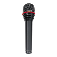
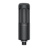
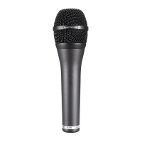
TG V70
TG V70 S
DYNAMISCHES MIKROFON
DYNAMIC MICROPHONE
MICROPHONE DYNAMIQUE
PRODUKTINFORMATION
PRODUCT INFORMATION
INFORMATIONS DE PRODUIT