12 -
LIBRA - Ver. 06
D811323_06
INSTALLATION MANUAL
ENGLISH
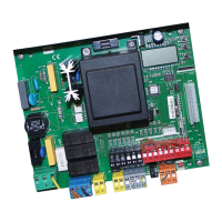
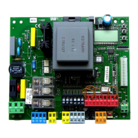
JP7
21-22 Output for gate-open warning light output (N.O. contact (24Va.c./
1A max)) or alternatively 2nd radio channel (see paragraph 5 on
“Configuration”)
23-24 Antenna input for radio-receiver plug-in board (23 braid–24
signal).
5) PROGRAMMING
The control panel provided with a microprocessor is supplied with function
parameters preset by the manufacturer, suitable for standard installations.
The predefined parameters can be altered by means of either the
incorporated display programmer or UNIPRO.
In the case where programming is carried out by means of UNIPRO,
carefully read the instructions relating to UNIPRO, and proceed in the
following way.
Connect the UNIPRO programmer to the control unit through the UNIFLAT
and UNIDA accessories (See fig. 4). The Libra control unit does not supply
the UNIPRO programmer with power, and therefore requires an appropriate
supply unit.
Enter the “CONTROL UNITS” menu, and the “PARAMETERS” submenu,
then scroll the display screenfuls using the up/down arrows to set the
numerical values of the parameters listed below.
For the function logics, refer to the “LOGIC” submenu.
In the case where programming is carried out by means of the incorporated
programmer, refer to Fig. A and B and to the paragraph on “Configuration”.
6) CONFIGURATION
The display programmer is used to set all the LIBRA control panel functions.
The programmer is provided with three pushbuttons for menu scrolling and
function parameter configuration:
+ menu scrolling/value increment key
- menu scrolling/value reduction key
OK Enter (confirm) key
The simultaneous pressure of the + and - keys is used to exit the active
menu and move to the preceding menu.
The modifications made are only set if the OK key is subsequently pressed.
When the OK key is pressed for the first time, the programming mode is
entered.
The following pieces of information appear on the display at first:
- Control unit software version
- Number of total manoeuvres carried out (the value is expressed in
thousands, therefore the display constantly shows 0000 during the first
thousand manoeuvres)
- Number of manoeuvres carried out since the latest maintenance operation
(the value is expressed in thousands, therefore the display constantly
shows 0000 during the first thousand manoeuvres)
- Number of memorised radio control devices.
When the OK key is pressed during the initial presentation phase, the first
menu can be accessed directly.
Here follows a list of the main menus and the respective submenus available.The
predefined parameter is shown between square brackets [ 0 ].
The writing appearing on the display is indicated between round brackets.
Refer to Figures A and B for the configuration procedure.
6.1) PARAMETER MENU (PARAm)
- Automatic Closing Time (TCA) [ 10s ]
Set the numerical value of the automatic closing time from 3 to 60
seconds.
- Motor 1 torque (Mot1 torque) [ 50% ]
Set the numerical value of the motor 1 torque between 1% and 99%.
- Motor 2 torque (Mot 2 torque) [ 50% ]
Set the numerical value of the motor 2 torque between 1% and 99%.
NOTE: In case of obstacle detection, the Ampere-stop function
halts the leaf movement, reverses its motion for 1 sec. and then
halts in the STOP status.
WARNING: Check that the impact force value measured at the
points established by the EN 12445 standard is lower than that
specified in the EN 12453 standard.
Incorrect torque setting can cause injuries to persons or animals,
or damage to things.
- Opening delay time (open delay time) [ 1s ]
Set the opening delay time for motor 1 relative to motor 2, between 1 and
5 seconds.
- Closing delay time (cls delay time) [ 1s ]
Set the closing delay time for motor 2 relative to motor 1, between 1 and
5 seconds.
- Zone (zone) [ 0 ]
Set the zone number between a minimum value of 0 and a maximum
value of 127. See paragraph 7 on “Serial connection”.
6.2) LOGIC MENU (logic.)
- TCA (TCA) [ OFF ]
ON Activates automatic closing
OFF Excludes automatic closing
- 3 Steps (3 step) [ OFF ]
ON Enables 3-step logic. A Start impulse has the following effects:
door closed: ............................................................................ opens
on opening: ............................ stops and enters TCA (if configured)
door open: .............................................................................. closes
on closing: .......................................................... stops and reopens
OFF Enables 4-step logic. A Start impulse has the following effects:
door closed: ............................................................................ opens
on opening: ............................ stops and enters TCA (if configured)
door open: .............................................................................. closes
on closing: ............................. stops and does not enter TCA (stop)
after stopping: ......................................................................... opens
- Impulse lock (ibl open) [ OFF ]
ON The Start impulse has no effect during the opening phase.
OFF The Start impulse becomes effective during the opening or closing
phase.
- Rapid closing (fast cls) [ OFF ]
ON Closes the gate after photocell disengagement, before waiting for
the end of the TCA set.
OFF Command not entered.
- Photocells on opening (photc. open) [ OFF ]
ON: In case of obscuring, this excludes photocell operation on opening.
During the closing phase, it immediately reverses the motion.
OFF: In case of obscuring, the photocells are active both on opening and
on closing. When a photocell is obscured on closing, it reverses the
motion only after the photocell is disengaged.
- Photocell test (test phot) [ OFF ]
ON Activates photocell check
OFF Deactivates photocell check
If this setting is not activated (OFF), it inhibits the photocell checking
function, allowing connection of devices not provided with additional
checking contact.
- Gate-open or 2nd radio channel warning light (signaling outp) [ OFF ]
ON The output between terminals 21 and 22 is configured as Gate-open
warning light, in this case the 2nd radio channel controls pedestrian
opening.
OFF The output between terminals 21 and 22 is configured as 2nd radio
channel.
- Motors in operation (1 mot ON) [ OFF ]
ON Only motor 2 is in operation (terminals 3, 4 and 5).
With this configuration, the pedestrian input is disabled.
OFF Both motors are in operation.
- Lock hold (block persist) [ OFF ] (Fig. 5)
ON To be used when the mechanical closing backstop is fitted.
This function activates leaf pressure on the mechanical backstop,
without this being considered as an obstacle by the Ampere-stop
sensor.
Therefore the rod continues its travel for another 0.5 sec. after
detecting the closing limit switch or upon reaching the mechanical
backstop. So by activating the closing limit switches slightly earlier,
the leaves will come to a perfect halt against the backstop.
(Fig. 5a)
OFF To be used when no mechanical closing backstop is fitted.
Movement is exclusively halted by activation of the closing limit
switches; in this case proceed to carrying out precise setting of the
closing limit-switch activation. (Fig. 5b)
- Master/Slave (Master) [ OFF ]
ON The control panel is set as Master in a centralised connection (see
Paragraph 7).
OFF The control panel is set as Slave in a centralised connection (see
Paragraph 7).
- Loop (loop) [ OFF ]
ON In the case of a closed loop centralised connection (Fig.7), set the
control unit to ON.
OFF In the case of an open centralised connection (Fig.7), set the control
unit to OFF.
6.3) RADIO MENU (RADIO)
- Add
Allows you to add one key of a radio control device to the receiver
memory; after storage it displays a message showing the receiver
 Loading...