Via Lago di Vico, 44
36015 Schio (VI)
Tel.naz. 0445 696511
Tel.int. +39 0445 696533
Fax 0445 696522
Internet: www.bft.it
E-mail: sales@bft.it
ISTRUZIONI DI INSTALLAZIONE
INSTALLATION MANUAL
INSTRUCTIONS D'INSTALLATION
MONTAGEANLEITUNG
INSTRUCCIONES DE INSTALACION
INSTRUÇÕES DE INSTALAÇÃO
D811395 ver.01 21-03-03
I
RADIOTRASMITTENTE BICANALE DA PARETE
WALL-MOUNTED DOUBLE-CHANNEL RADIO TRANSMITTER
ÉMETTEUR RADIO MURAL À DEUX CANAUX
ZWEIKANAL-FUNKSENDER FÜR DIE WANDMONTAGE
RADIOTRANSMISOR BICANAL DE PARED
RADIOTRANSMISSOR BICANAL DE PAREDE
GB
F
D
E
P
PR2
FIG. 1
FIG. 3FIG. 2
2 CR2016
LED
TN
T1
T2
OK!
C
B
B
A
S4
2,9x22 TPS
P1
BFT Torantriebssysteme GmbH
Johannisstr. 14,D-90763 Frth
Tel. 0049 911 773323
Fax 0049 911 773324
Parc Club des Aygalades
35 bd capitaine GEZE
13333 MARSEILLE Cedex 14
Tel. 0491101860
Fax 0491101866
BFT DEUTSCHLAND
BFT FRANCE
BFT S.p.a. ITALIA
Via Lago di Vico, 44
36015 Schio (VI)
Tel.naz. 0445 696511
Tel.int. +39 0445 696533
Fax 0445 696522
I nternet: www.bft.it
E- mail: sales@bft.it
http://www.bft-torantriebe.de
8 027908 218650
1) GENERALITÀ
Trasmettitore bicanale rolling code con frequenza 433,92 MHz, per
installazione a parete. L’uso previsto è per l’attivazione di apritaparelle,
basculanti, porte sezionali, ecc.
Il presente dispositivo può essere utilizzato nei paesi indicati in
copertina Confermiamo che è conforme alle seguenti direttive euro-
pee: 99/5/CEE.
1) DATI TECNICI
Alimentazione: ..................................... 2 batterie al litio tipo CR2016
Assorbimento: ................................................... 5 mA in trasmissione
Frequenza: ..................................................................... : 433.92MHz
Temperatura di funzionamento ......................................... : 0 / +55°C
Grado di protezione: ................................................................... IP 20
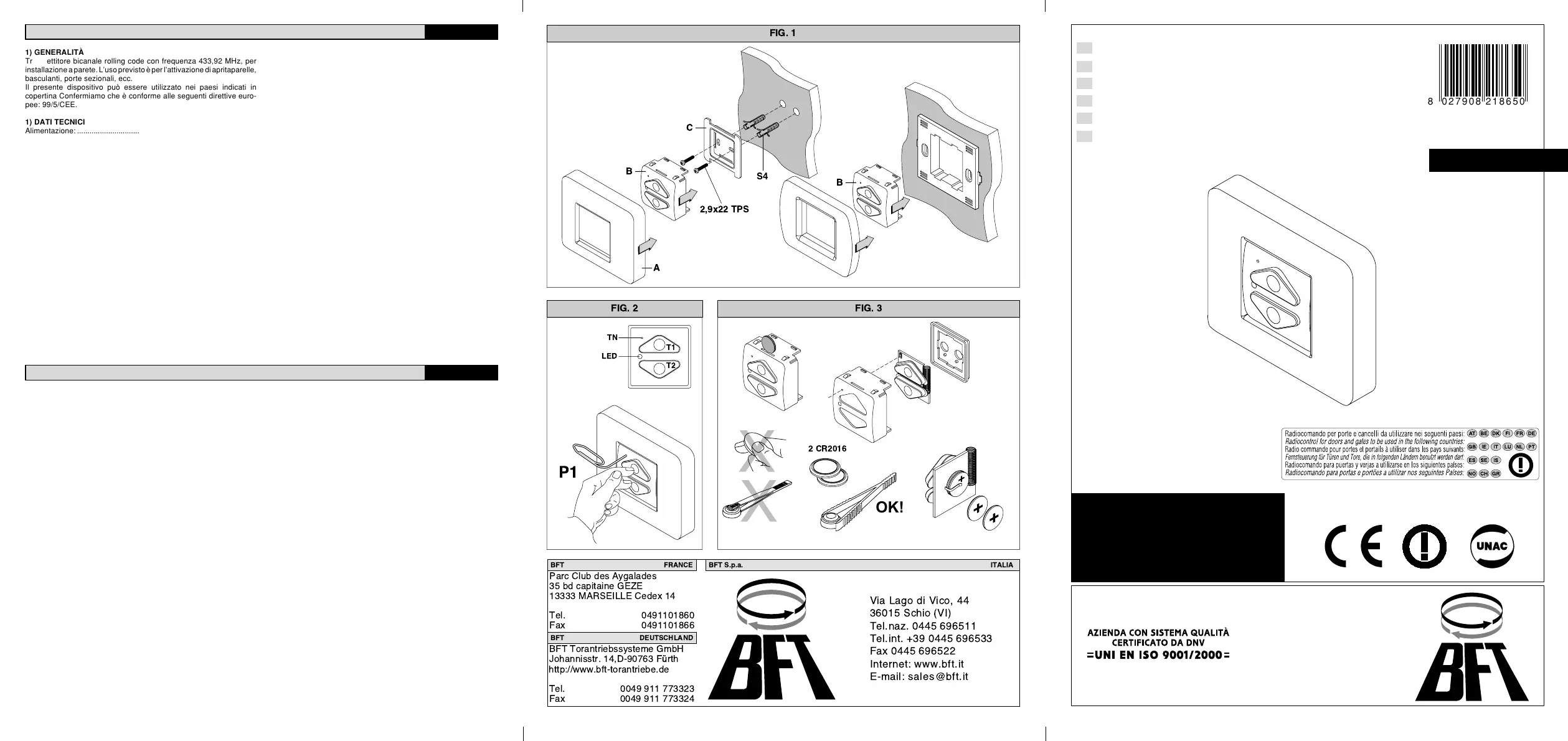
2) INSTALLAZIONE
Installazione a muro (Fig.1)
1) Posizionare il supporto C sul muro
2) Segnare il posizionamento delle forature necessarie per i 2
tasselli S4 (non forniti)
3) Dopo aver effettuato le forature fissare il supporto C con 2 viti
2,9x22 testa piana svasata (non fornite)
4) Agganciare il corpo trasmettitore B al supporto C
5) Agganciare il frontalino A al corpo del trasmettitore B
Installazione a incasso (Fig.1)
Il corpo del trasmettitore B è compatibile con le mascherine portafrutto
a due moduli di alcune marche. In questo caso agganciare il corpo
direttamente alla mascherina, quindi coprire con il frontalino appro-
priato. Il supporto C non è necessario.
3) PROGRAMMAZIONE (Fig.2)
La memorizzazione della trasmittente nella ricevente avviene secon-
do le modalità specifiche di ogni modello. Fate riferimento alle istruzio-
ni fornite con la ricevente. La funzione tasto nascosto (P1) si ottiene
MANUALE PER L’INSTALLAZIONE
ITALIANO
con la pressione simultanea dei due tasti T1 e T2 e del tasto TN.
Il tasto TN può essere premuto utilizzando una piccola graffetta.
4) SOSTITUZIONE BATTERIE (Fig.3)
Una diminuzione della portata della trasmittente può essere dovuta
alle batterie che si stanno scaricando. Quando il led della trasmittente
lampeggia, indica che le batterie sono scariche e devono essere
sostituite:
1) Rimuovere il frontalino e sganciare il corpo trasmettitore dalla sua
sede
2) Con una moneta fare leva nell’incavo posizionato sul lato superio-
re del corpo trasmettitore in modo da aprirlo
3) Sostituire le due batterie utilizzando esclusivamente batterie tipo
CR2016 prestando attenzione alle polarità. Il polo positivo deve
essere collegato alla lamella (Fig.3)
4) Verificare che i copritasti siano posizionati nella loro sede e
riposizionare la scheda nel contenitore prestando attenzione al
corretto orientamento. Il led presente nel trasmettitore deve
essere allineato al foro presente sul corpo.
4) AVVERTENZE
La presenza di parti metalliche (es. mascherina portafrutto) o di
umidità nei muri può ridurre la portata del sistema.
E’ buona norma evitare, se possibile di installare trasmettitori e
ricevitori vicino ad oggetti metallici voluminosi o in prossimità del
suolo. L’uso di comandi a distanza può essere causa di pericolo, si
raccomanda l’utilizzo di dispositivi di sicurezza adeguati.
Le descrizioni e le illustrazioni del presente manuale non sono
impegnative. Lasciando inalterate le caratteristiche essenziali
del prodotto, la Ditta si riserva di apportare in qualunque momen-
to le modifiche che essa ritiene convenienti per migliorare tecni-
camente, costruttivamente e commercialmente il prodotto, senza
impegnarsi ad aggiornare la presente pubblicazione.
1) GENERAL OUTLINE
Rolling-code double-channel transmitter with 433.92 MHz frequency,
to be mounted on the wall. Intended for operating roller shutters,
overhead doors, sectional doors etc.
The present device can be used in the countries mentioned on the
cover. We declare that it conforms to the following European directive:
EEC/99/5.
1) TECHNICAL SPECIFICATIONS
Power supply: ........................................... 2 CR2016 lithium batteries
Absorption: ....................................................... 5 mA on transmission
Frequency: ..................................................................... : 433.92MHz
Working temperature ....................................................... : 0 to +55°C
Degree of protection:………… .................................................... IP 20
2) INSTALLATION
Wall mounting (Fig.1)
1) Position support C on the wall.
2) Mark the position of the holes needed for the 2 plugs S4 (not
supplied).
3) Having drilled the holes, secure support C by means of 2 2.9x22
flat countersunk head screws (not supplied).
4) Fasten transmitter body B to support C.
5) Fasten front plate A to transmitter body B.
Recessed mounting (Fig.1)
Transmitter body B is compatible with the two-module support boxes
manufactured by certain brands. In this case, directly fasten the body
to the support box, then cover it with the appropriate front plate.
Support C is not needed.
3) PROGRAMMING (Fig.2)
Storage of the transmitter in the receiver memory is carried out according
to specific methods for each model. Make reference to the instructions
supplied with the receiver. The hidden key (P1) function is obtained by
simultaneously pressing the two keys T1 and T2 and key TN.
INSTALLATION MANUAL
ENGLISH
Key TN can be pressed using a small clip.
4) BATTERY REPLACEMENT (Fig.3)
A decrease in the transmitter range may be due to the batteries losing
charge. When the transmitter LED blinks, it means that the batteries
are exhausted and must be replaced:
1) Remove the front plate and release the transmitter body from its
seat.
2) Insert a coin in the slot on the upper transmitter body, and use it
as a lever to open it.
3) Replace the two batteries with new CR2016 batteries only, paying
attention to their polarity. The positive pole must be connected to
the blade (Fig.3)
4) Check that the key covers are positioned in their seats, and
reposition the board in the container, making sure it is placed the
right way round. The LED present in the transmitter must be
aligned with the hole present in the body.
4) WARNING
The presence of metallic parts (ex. support box) or dampness in the
walls can reduce the system range.
Whenever possible, it is a good rule to avoid installing transmitters and
receivers near large metallic objects or next to the ground. The use of
remote controls can cause danger, it is recommended to use adequate
safety devices.
The descriptions and illustrations contained in the present manual
are not binding. The Company reserves the right to make any
alterations deemed appropriate for the technical, manufacturing
and commercial improvement of the product, while leaving its
essential features unchanged, at any time and without undertaking
to update the present publication.
 Loading...