Do you have a question about the BFT SHYRA AC SL and is the answer not in the manual?
Crucial safety advice for product use to prevent injury and damage.
General safety guidelines and recommended behaviours for safe operation.
Proper disposal of electronic equipment and batteries according to regulations.
Crucial safety advice for installation to prevent injury and damage.
Product design, compliance, and general safety principles for installation.
Specific instructions and warnings for electrical connections and wiring.
Proper disposal of packaging materials and electronic waste.
Key for understanding symbols and indicators used in diagrams.
Diagrams for right and left boom assemblies installation.
Diagrams for right and left boom assemblies installation.
Code required for radio transmitter cloning and advanced receiver features.
Steps for setting parameters, automatic closing time, and work time.
Description of S1, S2, and S1+S2 button functions.
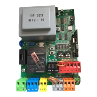
Explanation of LED status for Power, Start, Open, Stop, Phot, etc.
Table detailing LED error codes and their meanings.
Explains the function of each terminal on the control board.
DIP switch settings for safety device inputs (BAR, PHOT).
Details on connecting the antenna for radio reception.
Setting the waiting time before automatic closing.
Setting motor working time for SHYRA AC SL and BA models.
Enables/disables wireless transmitter memorization.
Configures input for resistive edge or safety edge.
Enables/disables safety check for photocell input.
Enables/disables safety check for BAR input.
Logic for photocell behaviour during opening and closing.
Defines safety edge operation modes for SHYRA AC SL/BA.
Configures the fast closing time after photocell clearance.
Sets the automation type: Residential or Apartment building.
| RF Frequency | 433.92 MHz |
|---|---|
| Number of Buttons | 4 |
| LED Indicator | Yes |
| Battery Type | CR2032 |
| RF Range | 100m |
| Battery Life | 2 years |