SW-Stahl und Werkzeugvertriebs GmbH Tel. +49 (0) 2191 / 46438-0
F 56 essartS resukreveL ax +49 (0) 2191 / 46438-40
ed.lhatsws@ofni :liaM-E diehcsmeR 79824-D
Instruction Manual
BGS technic KG
Bandwirkerstr. 3
42929 Wermelskirchen
Tel.: 02196 720480
Fax.: 02196 7204820
mail@bgs-technic.de
www.bgstechnic.com
© BGS technic KG, Copying and further use not allowed
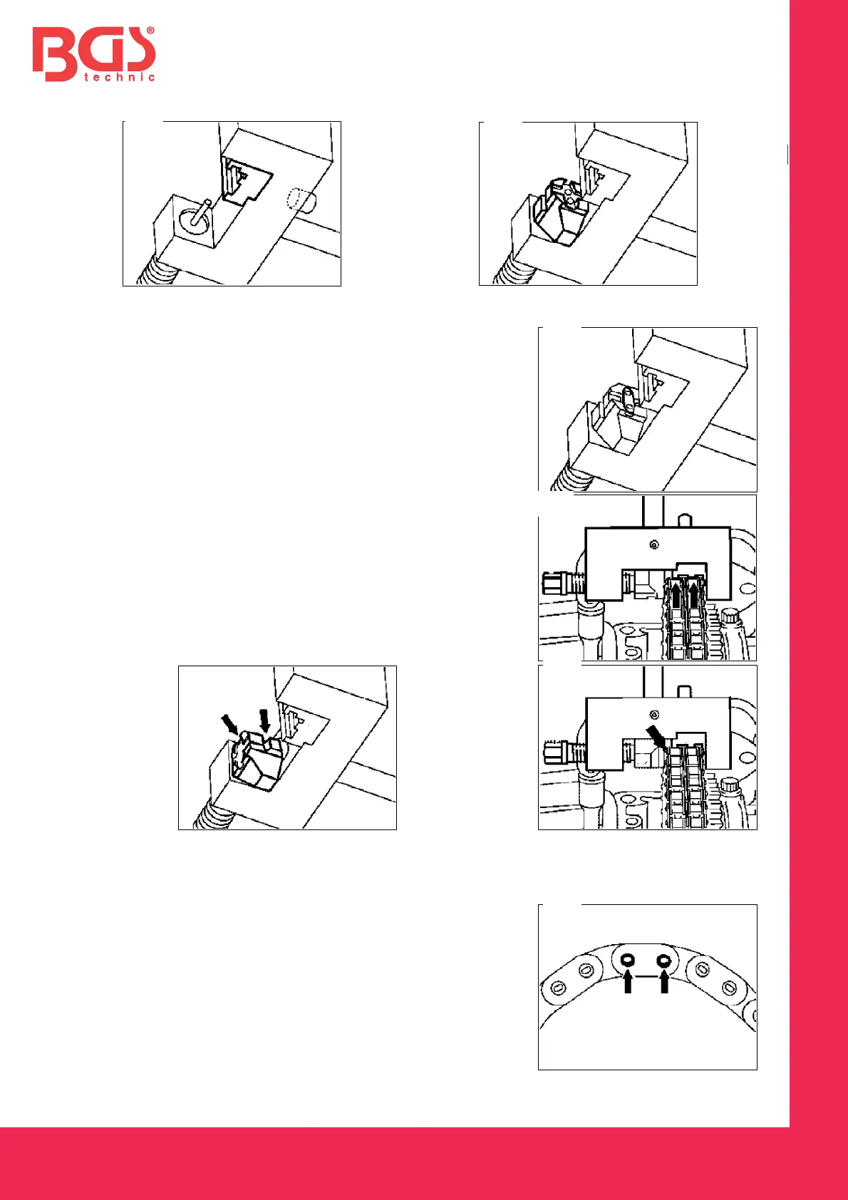
7. Place a suitable guiding tool into the holder and fix it with the screw (picture A).
8. Insert the movable pressure pad for the outer plate into the riveting tool (picture B).
9. Insert the outer plate into the pressure pad (picture C).
10. Place the tool such that the spacer studs (arrows) are
positioned on the rollers of the riveting link (picture D).
11. Screw in the spindle to the stop. Note: make sure while
turning the spindle that the bolts of the riveting link get
pressed into the bore holes of the outer plate.
12. Take off the tool.
13. Change the pressure pad to the riveting profile (arrow), (picture E).
14. Place the tool exactly over the middle of the bolt (arrow), (picture F).
15. Tighten the spindle. Tightening torque on the spindle 30 to 35 Nm.
16. Rivet every bolt on the riveting link individually.
17. Check riveting (arrow) and re-rivet, if necessary (picture G).
F